background image


Advanced Air UK Ltd 

Burrell Way 
Thetford 
Norfolk IP24 3QU 
Tel: 01842 765657 
Email: [email protected] 


2530 CE Series  

Smoke Fire Damper 


Due to continuous product development Advanced 
(U.K.) Ltd reserves the right to change any 
information without prior notice 

Date 

Issue 

Sheet 

Spec Number 

April 2018 

30 of 34 

TS2530CE-01 


G:\PRODUCTS\DMP - 2500 Series\05 Product Data\2530\Tech Sub\2530CE\TS2530CE-01 Technical Sub Rev C.docx 

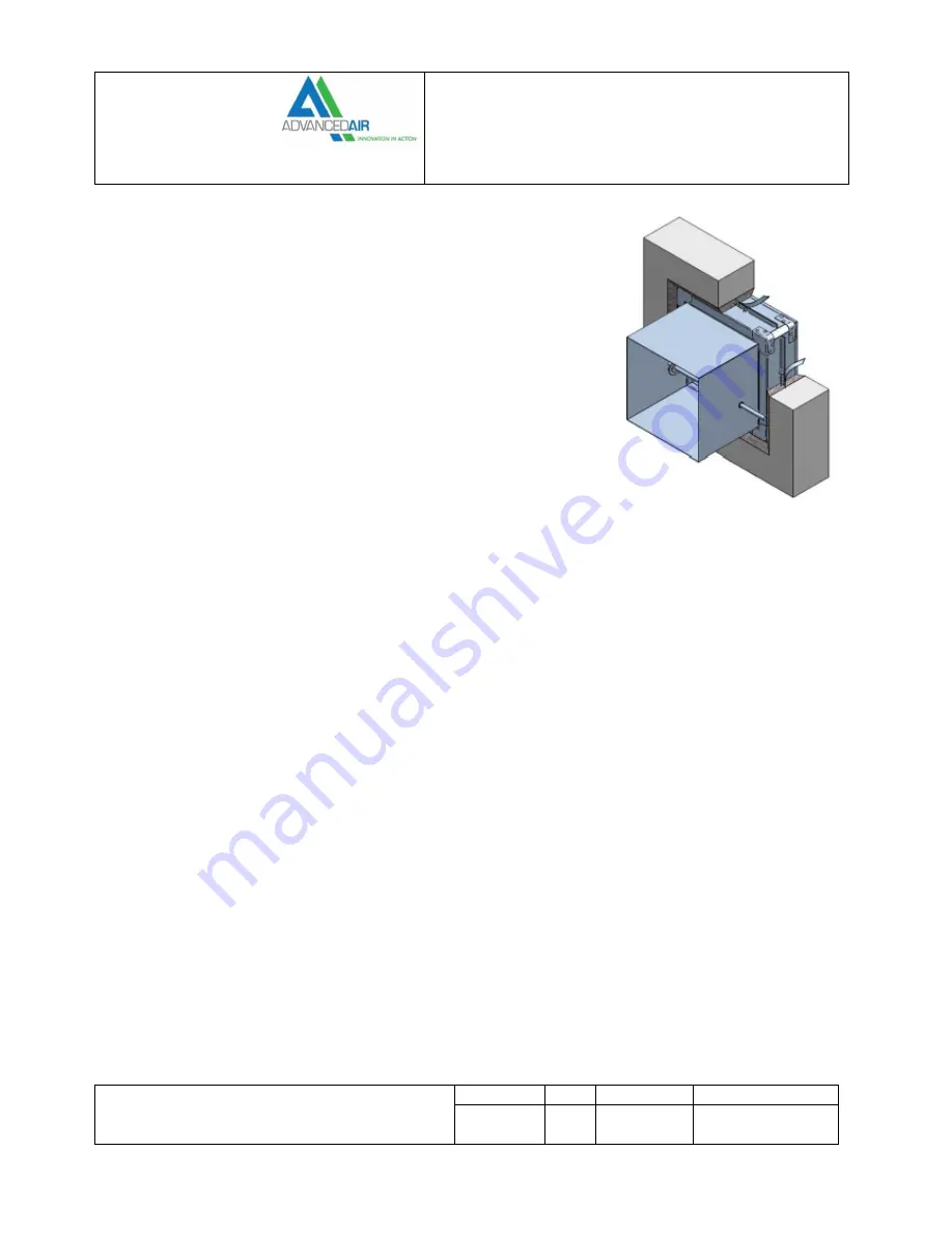
Blockwork wall HEVAC frame 

Classification 

E120 (ve i↔o)S 

Pre Installation Notes 

1.


Ensure that the damper is kept in a clean dry environment. 

2.


Remove all packaging and any transit ties and check that the damper frame and 
blades are clean and free of any freight matter. 

3.


Examine the assembly for distortion, denting or surface damage which could 
inhibit the operation of the damper. 

4.


Operate the damper blades in the appropriate mounting position. It is important 
that the blades operate freely and without undue pressure being applied. 

Installation Procedure 

1.


Vertical builders work barrier to have an appropriately sized lintel to ensure an 
opening clearance for the expansion frame. 

2.


The opening in the wall must be cleaned, free of dust and any other contaminants which could impair the mortar 
adhesion. A clearance gap 25mm (min) to 50mm (max) must be maintained around the expansion frame of the damper 
(barrier contractor). 

3.


The damper shall be fitted centrally in the wall opening. 

4.


The tabs on the factory fitted galvanised steel expansion frame shall be bent out to tie the damper into the wall with the 
penetration seal. 

5.


The ‘Penetration Seal’ must have a structural and fire rated compatibility with both the barrier and the damper and have 
sufficient strength to retain the fire damper within the wall in a fire situation. (4:1 mortar mix). 

6.


The mortar mix will be applied up to the installation frame face, take care not to leave any air pockets in the mix. 

7.


The ductwork connecting to the damper spigots must overlap by 40mm, leaving a 10mm clearance for any duct expansion 
in a fire situation. 

8.


All ductwork connections must be sealed with an approved ductwork sealer, and fixed with low resistance fixings such as 
aluminium alloy rivets or nylon bolts. 

9.


All connecting ductwork must be independently supported within 1m of the connections. 

10.


An access cover should be fitted on the appropriate side of the barrier to enable inspections and maintenance work. 


Summary of Contents for 2530 CE Series

Page 1: ...ion The model 2530 is designed to prevent the spread of fire and smoke through ventilation ductwork in walls and floors When the power to the damper actuator is removed the actuator spring is released...

Page 2: ...Corners Welded mitre corners finished with aluminium aerosol spray Seals Options Semi Sealed Fitted with stainless steel side jamb seals Due to the unique design of the damper blades blade seals are n...

Page 3: ...will be split and shipped as separate pieces each piece being no larger than a duct size of 2050mm x 2050mm Below are the minimum and maximum sizes possible Available in 1mm increments Duct Size Rect...

Page 4: ...ts and rotated COM Both orientation of blades typically on multi section units Duct Connection C Circular Spigot Connection O Flat Oval Spigot Connection R Square or Rectangular Spigot Connection Fram...

Page 5: ...damper we will supply a multi section damper instead A multi section damper is one that is made up of 2 or more single dampers Wherever possible these single dampers are joined in the Advanced Air fac...

Page 6: ...Frame The installation frame is factory fitted to its respective fire damper and the assembly is delivered to site as one unit It removes the need for sleeve and angle fitting and allows expansion of...

Page 7: ...fers a versatile way to install a damper that can be easily re positioned if necessary whilst also allowing the installation of the damper itself to be carried by the ductwork contractor before the bu...

Page 8: ...p of the damper to prevent blades dragging on the bottom seals Drive location DTOP Drive top This signifies that the drive is at the top The actuator shall be fitted at the top of the damper and the b...

Page 9: ...e bottom The outer dampers will therefore have horizontal blades and the centre dampers will have vertical blades On vertical blade dampers spacers will be fitted to the linkage at the top of the damp...

Page 10: ...ded orientation Examples are shown below For dampers with Horizontal orientated blades These would be coded H Horizontal Left LH AMH Horizontal Right RH AMH Vertical Left LH AMVD Vertical Right RH AMV...

Page 11: ...ounting accessories On a vertical bladed damper spacers will be fitted to the linkage at the top of the damper The orientation of mounting accessories e g AFS frame will be re positioned to suit insta...

Page 12: ...tion dampers with three sections will have a centre section with vertical blades The centre section can have the actuator at the top and at bottom These configurations would be coded as COMT External...

Page 13: ...72 C Thermal fuse The 2530 series is fitted with 3 thermal fuses which work together to provide a total fire safety solution There are 2 thermal fuses for monitoring the duct temperature and one for t...

Page 14: ...serves the right to change any information without prior notice Date Issue Sheet Spec Number April 2018 C 14 of 34 TS2530CE 01 G PRODUCTS DMP 2500 Series 05 Product Data 2530 Tech Sub 2530CE TS2530CE...

Page 15: ...uct Data 2530 Tech Sub 2530CE TS2530CE 01 Technical Sub Rev C docx Wiring configurations and options Wiring on standard dampers and standard multi section dampers As standard a single section damper w...

Page 16: ...y information without prior notice Date Issue Sheet Spec Number April 2018 C 16 of 34 TS2530CE 01 G PRODUCTS DMP 2500 Series 05 Product Data 2530 Tech Sub 2530CE TS2530CE 01 Technical Sub Rev C docx W...

Page 17: ...ange any information without prior notice Date Issue Sheet Spec Number April 2018 C 17 of 34 TS2530CE 01 G PRODUCTS DMP 2500 Series 05 Product Data 2530 Tech Sub 2530CE TS2530CE 01 Technical Sub Rev C...

Page 18: ...te Issue Sheet Spec Number April 2018 C 18 of 34 TS2530CE 01 G PRODUCTS DMP 2500 Series 05 Product Data 2530 Tech Sub 2530CE TS2530CE 01 Technical Sub Rev C docx Multi section 24VAC DC All dotted line...

Page 19: ...ate Issue Sheet Spec Number April 2018 C 19 of 34 TS2530CE 01 G PRODUCTS DMP 2500 Series 05 Product Data 2530 Tech Sub 2530CE TS2530CE 01 Technical Sub Rev C docx Multi section 230VAC All dotted lines...

Page 20: ...products are shipped in is not weather proof or fire resistant Approximate Weights kg Width mm 100 200 300 400 500 600 700 800 900 1000 Height mm 100 7 8 10 12 13 15 17 18 21 25 200 8 9 11 13 15 17 18...

Page 21: ...e Fire Damper Due to continuous product development Advanced U K Ltd reserves the right to change any information without prior notice Date Issue Sheet Spec Number April 2018 C 21 of 34 TS2530CE 01 G...

Page 22: ...Smoke Fire Damper Due to continuous product development Advanced U K Ltd reserves the right to change any information without prior notice Date Issue Sheet Spec Number April 2018 C 22 of 34 TS2530CE 0...

Page 23: ...ate Issue Sheet Spec Number April 2018 C 23 of 34 TS2530CE 01 G PRODUCTS DMP 2500 Series 05 Product Data 2530 Tech Sub 2530CE TS2530CE 01 Technical Sub Rev C docx Dimensions AFS with rectangular spigo...

Page 24: ...er Due to continuous product development Advanced U K Ltd reserves the right to change any information without prior notice Date Issue Sheet Spec Number April 2018 C 24 of 34 TS2530CE 01 G PRODUCTS DM...

Page 25: ...Date Issue Sheet Spec Number April 2018 C 25 of 34 TS2530CE 01 G PRODUCTS DMP 2500 Series 05 Product Data 2530 Tech Sub 2530CE TS2530CE 01 Technical Sub Rev C docx HEVAC frame with rectangular spigot...

Page 26: ...Due to continuous product development Advanced U K Ltd reserves the right to change any information without prior notice Date Issue Sheet Spec Number April 2018 C 26 of 34 TS2530CE 01 G PRODUCTS DMP...

Page 27: ...kwork wall AFS Motorised fire damper installed with AFS frame single section and multi section Min 100x100mm Max 1000x1000mm single section No stated maximum size if multi section BRE 289678 BRE 28968...

Page 28: ...nt ductwork to facilitate the inspection and maintenance Ensure no physical restriction of the blades has occurred during the installation process Remove any dirt or debris built up in the damper appl...

Page 29: ...ately sized lintel and opening clearance for the damper and Firebatt 2 The opening in the wall must be cleaned free of duct and any other contaminants which could impair the acrylic sealant A clearanc...

Page 30: ...expansion frame 2 The opening in the wall must be cleaned free of dust and any other contaminants which could impair the mortar adhesion A clearance gap 25mm min to 50mm max must be maintained around...

Page 31: ...ssure being applied Installation Procedure 1 The Drywall which will consist of two layers of 15mm plasterboard each side of the steel studwork with a 50mm Rockwall insulation The opening will be a let...

Page 32: ...casing barrier contractor 2 The damper shall be mounted so that the top edge of the frame is flush with the surface of the floor slab It shall be fixed using AFS angle slotted rail 40x40x4mm supplied...

Page 33: ...of the damper barrier contractor 2 The tabs on the factory fitted galvanised steel expansion frame will be bent out to tie the damper into the floor with the penetration seal 3 The damper should be f...

Page 34: ...to change any information without prior notice Date Issue Sheet Spec Number April 2018 C 34 of 34 TS2530CE 01 G PRODUCTS DMP 2500 Series 05 Product Data 2530 Tech Sub 2530CE TS2530CE 01 Technical Sub...

Reviews: