Single-channel all-digital AC servo drives QS7 Series
28
P4
Control
mode
0
-
Position mode: external pulse input;
1
-
JOG mode: key control;
2
-
Speed mode: external analog voltage input;
3
-
Torque mode: external analog voltage input;
4
-
Position and speed mode: MODE control;
5
-
Position and torque mode: MODE control;
6
-
CW CCW: external signal JOG mode
7
-
4 sections speed control
0
-
7
P5
Servo
enable
control
0
-
Valid
1
-
Invalid: forcibly lock shaft
0
-
1
P6
Servo input
signal
INTH
function
0
-
Invalid
1
-
Input pulse prohibition and position deviation clear
2
-
Input pulse prohibition and position deviation not clear
0
-
1
P7
Limit input
control
0
-
Invalid;
1
-
Active LOW without alarm;
2
-
Active HIGH without alarm;
3
-
Active LOW with alarm;
4
-
Active HIGH with alarm;
0
-
4
P8
Coin
output
mode
0
-
Orientation completion
1
-
Torque reaching
2 – Output when speed is less than P49 speed (When P49 <
10rpm, it is handled upon 10rpm.)
0
-
2
P9
Alarm
output
mode
0
-
Normal close type
1
-
Normal open type
0
-
1
P10
Pulse mode
0
-
Pulse
+
direction: normal direction;
1
-
Pulse
+
pulse: normal direction
2
-
Orthogonal pulse: normal direction
0
-
2
P11
Motor
direction
0
-
Normal
1
-
Reverse
0
-
1
P12
Electronic
gear
numerator
Sub-octave of position command pulse is set (E-gear);
Under the mode of position control, a variety of pulse
sources matching can be facilitated through P12 and P13
parameters setup; this value should increase as far as
possible under the consideration for drive to accept
frequency range less than 500K.
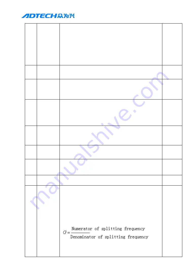
P×G=N×C×4
P: Pulses entered into the command
G: E-gear ration
N:Motor rotations
C:Optical encoder lines
;
generally it is 2500 lines
〖
Example
〗
When command pulse is required to input
1
-
32000


