background image

Windows Driver Installation

 47

4.3 LAN Driver Installation 

This section describes the LAN driver installation for the Intel®
82546EB onboard Ethernet controllers. 

1. Run pro2kxp.exe located in the following directory:

X:\cPCI\cPCI-3840\LAN.

2. Read the license agreement. Click 'I accept the terms in

the license agreement’ if you agree to continue.

3. Location to Save Files, click Next to save files in folder.

4. Intel® PRO Network Connections. Click Install Software

to install drivers and Intel® PROSet.

4.4 Audio Codec Driver Installation 

This section describes the LAN driver installation for the Intel®
82546EB onboard Ethernet controllers. 

1. The driver is included in the driver CD. Run

wdm_a357.exe located in the following directory:
X:\cPCI\cPCI-3840\Audio.

2. Click ‘Next’ on the Welcome audio setup screen to install

driver..

3. Finally, click 'Finish' to re-start.

Artisan Technology Group - Quality Instrumentation ... Guaranteed | (888) 88-SOURCE | www.artisantg.com

Summary of Contents for cPCI-3840 Series

Page 1: ...service in house repair center WE BUY USED EQUIPMENT Sell your excess underutilized and idle used equipment We also offer credit for buy backs and trade ins www artisantg com WeBuyEquipment REMOTE IN...

Page 2: ...World Manual Rev 2 01 Revision Date December 18 2006 Part No 50 15034 100 cPCI 3840 Series 3U CompactPCI Pentium R M CPU Module User s Manual Artisan Technology Group Quality Instrumentation Guarantee...

Page 3: ...ty to use the product or documentation even if advised of the possibility of such damages This document contains proprietary information protected by copy right All rights are reserved No part of this...

Page 4: ...2 82265717 Address 9F No 166 Jian Yi Road Chungho City Taipei 235 Taiwan Please email or FAX this completed service form for prompt and satisfactory service Company Information Company Organization Co...

Page 5: ...Artisan Technology Group Quality Instrumentation Guaranteed 888 88 SOURCE www artisantg com...

Page 6: ...ons 11 I O Connectivity Table 12 1 4 Unpacking Checklist 12 2 Jumpers and Connectors 15 2 1 cPCI 3840 Board Outline 16 2 2 cPCI 3840 Connector Pin Assignments 17 USB Connectors 17 Ethernet RJ 45 Conne...

Page 7: ...stallation 36 3 5 Heat Sink Installation 36 3 6 2 5 HDD Installation 40 3 7 cPCI 3840 CPU Module Installation 42 3 8 RTM Installation 43 4 Windows Driver Installation 45 4 1 Chipset Drivers Installati...

Page 8: ...nnectivity 12 Table 2 1 Jumper and Connector Locations 16 Table 2 2 Ethernet LED Status 18 Table 2 3 Switches and Jumpers 23 Table 2 4 CN5 CF Master Slave Setting 24 Table 2 5 JP2 Clear CMOS 25 Artisa...

Page 9: ...f cPCI R3840 27 Figure 3 1 CPU Installation 32 Figure 3 2 Memory Module Installation Pt 1 33 Figure 3 3 CPU Core Module Removal 34 Figure 3 4 Memory Module Installation Pt 2 35 Figure 3 5 Thermal Pad...

Page 10: ...Prefetch Logic Streaming SIMD Extensions 2 SSE2 a 400 MHz Source Synchronous pro cessor system bus and Advanced Power Management features including Enhanced Intel SpeedStep technology The Intel Pentiu...

Page 11: ...d hub interface HI 1 5 The 6300ESB s functions and capabilities include an 8 Bit Hub Interface a PCI X bus which supports 64 bit 66MHz operations a PCI Local Bus which supports 32 bit 33MHz operations...

Page 12: ...Introduction 3 Figure 1 1 cPCI 3840 Architecture Artisan Technology Group Quality Instrumentation Guaranteed 888 88 SOURCE www artisantg com...

Page 13: ...bit with ECC SODIMM X One VGA output supports resolution up to 1600 x 1200 at 85Hz and up to 2048 x 1536 at 75Hz X Digital display interface supports one port DVO with 165MHz output clock on each 12 b...

Page 14: ...n 2 2 The throughput of this PCI bus interface is 132 MB s and it supports 44 bit addressing using DAC protocol The 6300ESB also supports one PCIX 66MHz 64 bits interface which is compliant with the P...

Page 15: ...ent detection on all USB ports is supported USB legacy devices such as keyboard mouse and floppy drive are supported and can be enabled disabled in BIOS options In addition USB devices boot feature is...

Page 16: ...g system and CPU voltages and system temperature All hardware health status can be accessed in the BIOS options menu and using run time utilities In addition once the preset thresholds of the hardware...

Page 17: ...Memory Controller Hub GMCH X Intel 6300ESB I O Hub Controller Host Memory X Two SODIMM sockets 2GB maximum X Supports DDR266 333 SDRAM with ECC capability BIOS X Phoenix Award Plug and Play BIOS with...

Page 18: ...ntel 6300ESB south bridge X Bus master IDE controller supports ultra ATA 100 interface X Primary IDE on SBC with 44 pin IDE connector A 2 5 IDE HDD can be mounted X All USB ports are USB Spec Rev 2 0...

Page 19: ...cell CR2032 battery used for RTC and nonvolatile memory Environment X Operating ambient temperature 5 to 55 C X Storage temperature 20 to 80 C X Humidity 5 to 95 non condensed X Shock 15G peak to pea...

Page 20: ...X One GbE ports on RJ 45 connector X One DVI connector X One COM2 port on DB 9 connector X One USB port Full Loading 5V 3 3V Total Power Pentium M 1 6GHz CPU 512MB x 2 DDR 40G HD 3 16A 2 39A 23 6878 W...

Page 21: ...ADLINK Check the following items are included in the package if there are any missing items contact your dealer I O cPCI 3840 cPCI R3840 Face plate On board Face plate On board Serial Port COM1 DB 9 S...

Page 22: ...packing contents of cPCI 3840 OEM non standard con figurations may vary and is dependent on customer re quests This board must be protected from static discharge and physical shock Never remove any of...

Page 23: ...14 Introduction Artisan Technology Group Quality Instrumentation Guaranteed 888 88 SOURCE www artisantg com...

Page 24: ...familiarize themselves with the products before use The following sections are included X cPCI 3840 board outline X cPCI 3840 connectors pin assignments X cPCI 3840 jumpers setting X cPCI R3840 RTM b...

Page 25: ...and Top View Figure 2 2 cPCI 3840 Carrier Board Top View A Clear CMOS jumper JP2 C CF connector IDE0 B Slim type IDE IDE1 D CF master slave CN5 Table 2 1 Jumper and Connector Locations C B A D Artisa...

Page 26: ...Data2 4 LAN_RDP3 Receive Data3 5 LAN_RDN3 Receive Data3 6 LAN_RDN2 Receive Data2 7 LAN_TDP4 Transmit Data4 8 LAN_TDN4 Transmit Data4 Status Left LED Amber Right LED Yellow or Amber Network link is no...

Page 27: ...BaseT Link Amber Amber Active Blinking Amber Amber Signal Name Pin Pin Signal Name Red 1 2 Green Blue 3 4 N C GND 5 6 GND GND 7 8 GND 5V 9 10 GND N C 11 12 DDCDAT HSYNC 13 14 VSYNC DDCCLK 15 Artisan...

Page 28: ...eive data 3 TXD Transmit data 4 DTR Data terminal ready 5 IsoGND Isolated ground 6 DSR Data set ready 7 RTS Request to send 8 CTS Clear to send 9 RI Ring indicator Pin Signal Pin Signal 1 GND 5 RXN 2...

Page 29: ...DDP12 DDP2 13 14 DDP13 DDP1 15 16 DDP14 DDP0 17 18 DDP15 GND 19 20 NC PDDREQ 21 22 GND PDIOWJ 23 24 GND PDIORJ 25 26 GND PIORDY 27 28 PCSEL PDDACKJ 29 30 GND IRQ14 31 32 NC DAP1 33 34 DIAG DAP0 35 36...

Page 30: ...28 DD12 45 IDEACTJ 12 GND 29 DD13 46 DIAG 13 5V 30 DD14 47 DD8 14 GND 31 DD15 48 DD9 15 GND 32 CS3J 49 DD10 16 GND 33 GND 50 GND 17 GND 34 SDIORJ LED Color Status Description IDE Media Access Red OFF...

Page 31: ...D 33 GND AD 32 GND 13 GND AD 38 GND V I O 1 AD 37 AD 36 GND 12 GND AD 42 AD 41 AD 40 GND AD 39 GND 11 GND AD 45 GND V I O 1 AD 44 AD 43 GND 10 GND AD 49 AD 48 AD 47 GND AD 46 GND 9 GND AD 52 GND V I O...

Page 32: ...GND 11 GND IYAM0 IYAM1 IYAM2 IYAM3 ICLKAM GND 10 GND IYAP0 IYAP1 IYAP2 IYAP3 ICLKAP GND 9 GND IYBM0 IYBM1 IYBM2 IYBM3 ICLKBM GND 8 GND IYBP0 IYBP1 IYBP2 IYBP3 ICLKBP GND 7 GND CTS DSR RTS DTR NC GND...

Page 33: ...Clear CMOS JP2 JP2 is 3 pin jumper that can be used to clear the CMOS memory see Figure above for its location on the carrier board The CMOS RAM stores the real time clock RTC information BIOS configu...

Page 34: ...0 CPU Module from chassis 2 Short pins 2 and 3 of JP2 then reinstall the jumper to normal location 3 Insert the CPU Module back into the chassis Status JP2 Normal operation Default Clear CMOS Table 2...

Page 35: ...s a rear transition module designed for the cPCI 3840 It comes with one LAN port one USB port one DVI connec tor and one DB 9 serial port Figure 2 3 cPCI R3840 Front View and Top View Artisan Technolo...

Page 36: ...Jumpers and Connectors 27 Figure 2 4 Side View of cPCI R3840 Artisan Technology Group Quality Instrumentation Guaranteed 888 88 SOURCE www artisantg com...

Page 37: ...le Please refer to Section 2 2 The pin assignments for the DVI connector and RJ2 connector are as follows DVI Connector Pin Signal Pin Signal 1 TX2 16 HTPLG 2 TX2 17 TX0 3 GND 18 TX0 4 NC 19 GND 5 NC...

Page 38: ...GND VIO GL_MDIB3 GL_MDIB2 GND RJ2 12 COM2_CTSJ COM2_DCDJ COM2_DSRJ GND GL_MDIB3 GND RJ2 11 COM2_RTSJ GND VIO GL_MDIB0 GL_MDIB0 GND RJ2 10 TMDS_TXCP TMDS_TXCN RESERVE GND GL_MDIB1 GND RJ2 9 TMDS_HPDET...

Page 39: ...30 Jumpers and Connectors Artisan Technology Group Quality Instrumentation Guaranteed 888 88 SOURCE www artisantg com...

Page 40: ...stallation X CPU Core Module removal and installation X Heat sink and 2 5 HDD installation X cPCI 3840 CPU Module installation X cPCI 3840 RTM installation Depending on the options selected for your c...

Page 41: ...place it carefully in the CPU socket as shown in Figure 4 below Be sure to align the gold triangle on the corner of the chip with the corner of the socket that is missing a pin Press down gently on th...

Page 42: ...le Please refer to the figure below to install the first memory module Insert the module at a 30 degree angle and push the module firmly but gently into the slot until the security latches on the sock...

Page 43: ...ule by loosening the 4 screws that attach it to the carrier board Then carefully lift it upwards by grasping it with thumb and forefinger at the points marked GRIP HERE shown in Figure 5b This will pr...

Page 44: ...mory module into the slot shown in the figure below using the same procedure as described above for installa tion of the first memory module Figure 3 4 Memory Module Installation Pt 2 Artisan Technolo...

Page 45: ...stallation In order to properly dissipate heat from the CPU a heat sink is provided and must be installed before using the cPCI 3840 CPU Module First remove the transparent Mylar film from the white s...

Page 46: ...3 5 Thermal Pad Apply the thermal pad to the CPU white side down and remove the Mylar film from the top pink side of the thermal pad Artisan Technology Group Quality Instrumentation Guaranteed 888 88...

Page 47: ...Heat Sink Fitting Remove the Mylar Film covering the gray thermal pad on raised block Note orientation of heat sink to 855GME North Bridge Artisan Technology Group Quality Instrumentation Guaranteed 8...

Page 48: ...Heat Sink Screws Remove the Mylar Film covering the gray thermal pad on raised block Note orientation of heat sink to 855GME North Bridge Artisan Technology Group Quality Instrumentation Guaranteed 88...

Page 49: ...lation To install a 2 5 hard drive it is first necessary to install the mount ing brackets Follow the figure below for the installation procedure Artisan Technology Group Quality Instrumentation Guara...

Page 50: ...Getting Started 41 Then attach the IDE connector Figure 3 8 HDD and Mounting Bracket Installation Artisan Technology Group Quality Instrumentation Guaranteed 888 88 SOURCE www artisantg com...

Page 51: ...es of the board with the card guides on the chassis then slide the board into the chassis until resistance is felt 4 Move the locking handle in an inward direction until it is fully latched Note that...

Page 52: ...series and related RTMs make sure the RTM is the correct matching model Note Use the correct RTM to enable functions I O interfaces on rear side The RTM or system board can be damaged if the incorrect...

Page 53: ...44 Getting Started Artisan Technology Group Quality Instrumentation Guaranteed 888 88 SOURCE www artisantg com...

Page 54: ...fore installing any driver Most of the standard I O device drivers are included in Windows 2 Install the chipset driver 3 Install the graphics driver and utilities 4 Install the LAN drivers It is reco...

Page 55: ...ck Next on the Readme Information screen to install INF files 7 Click Finish to restart the system when prompted to do so 8 Follow the screen instructions and use the default set tings to complete set...

Page 56: ...k Next to save files in folder 4 Intel PRO Network Connections Click Install Software to install drivers and Intel PROSet 4 4 Audio Codec Driver Installation This section describes the LAN driver inst...

Page 57: ...48 Windows Driver Installation Artisan Technology Group Quality Instrumentation Guaranteed 888 88 SOURCE www artisantg com...

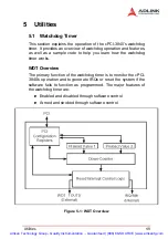
Page 58: ...ks WDT Overview The primary function of the watchdog timer is to monitor the cPCI 3840 s operation and to generate IRQs or reset the system if the software fails to function as programmed The major fe...

Page 59: ...system is reset The WDT of 6300ESB also supports multiple modes WDT and free running Free running mode is a one stage timer and it will toggle WDT_TOUT after programmable time WDT mode is a two stage...

Page 60: ...ll reload the down counter s value Following is the procedure of how to prevent a timeout 1 Write 80H to offset BAR 0CH 2 Write 86H to offset BAR 0CH 3 Write a 1 to RELOAD 8 of the reload register Off...

Page 61: ...ted as follows The GPIO control base port is 480H WDT_TOUT pin selection The WDT_TOUT signal is multiplexed with GPIO32 When using WDT this signal must be switched to WDT_TOUT func tion It uses bit 0...

Page 62: ...ke sure WDT_TOUT signal is functional Not GPIO32 function 3 Set WDT output enable presecaler and interrupt type into WDT configuration register 4 Obtain control base from Base Address register 5 Progr...

Page 63: ...rver in the network with one or more servers running PXE and MTFTP services It could be a Windows NT or Windows 2000 server running DHCP PXE and MTFTP service or a dedi cated DHCP server with one or m...

Page 64: ...l be covered by the original manufactur ers warranty X For products containing storage devices hard drives flash cards etc please back up your data before send ing them for repair ADLINK is not respon...

Page 65: ...eries by customer user X Damage from improper repair by unauthorized ADLINK technicians X Products with altered and or damaged serial numbers are not entitled to our service X This warranty is not tra...

Page 66: ...service in house repair center WE BUY USED EQUIPMENT Sell your excess underutilized and idle used equipment We also offer credit for buy backs and trade ins www artisantg com WeBuyEquipment REMOTE IN...

Reviews: