36
Getting Started
3.3 CF Card Installation
The CF card slot is located on the carrier board of the cPCI-3840.
The CF card can be inserted and ejected with the CPU Core Mod-
ule in place. However, if you are installing a second memory mod-
ule, it is easier to install the CF card when the CPU Core Module
has been removed.
3.4 CPU Core Module Installation
If you have removed the CPU Core Module to install a second
memory module, you must reattach it to the carrier board. Align
the 4 screw holes as shown in the figure above so that the board-
to-board connector sockets of the CPU Core Module and carrier
board meet properly. Then gently press down on the CPU Core
Module at the points marked GRIP HERE shown in Figure 5b until
it is firmly seated on the carrier board. Do not replace the screws
until after you have installed the heat sink as described in Section
3.5 below.
3.5 Heat Sink Installation
In order to properly dissipate heat from the CPU, a heat sink is
provided and must be installed before using the cPCI-3840 CPU
Module. First, remove the transparent Mylar film from the white
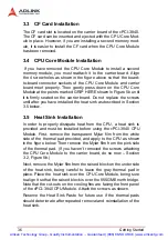
side of the thermal pad provided, and apply to the CPU as shown
in the figure below. Then remove the Mylar film from the pink side
of the thermal pad. (If you haven’t removed the screws attaching
the CPU Core Module to the carrier board, do so now – Section
3.2, Figure 5b.)
Next, remove the Mylar film from the raised block on the underside
of the heat sink, being careful to leave the gray thermal pad in
place. Place the heat sink over the CPU Core Module, being sure
to align it so that the raised block is over the 855GME north bridge.
Note that the cut-outs on the cooling fins are facing the front panel
of the cPCI-3840 CPU Module. Attach the screws as shown.
Reserve the Heat Sink Paste for future use if the thermal pads
should deteriorate after repeated removal and reinstallation of the
heat sink.
Artisan Technology Group - Quality Instrumentation ... Guaranteed | (888) 88-SOURCE | www.artisantg.com


