


CM
/
C
OMMISSIONING
M
ANUAL
27
3.12.7 The environment variable FBCH?
Feedback channel: An available analog input can be allocated to an analog actual value channel. This
variable is only significant for axes with motor types “ANALOG PWM” (Section 3.12.1.4), “ANALOG /
ANALOG” (Section 3.12.1.6), “CI_ANALOG” and “CD_ANALOG” (Section 3.12.1.16).
FBCHx y: x is the index of the axis to which the channel is assigned; y is the index of the analog input (0...7)
or of the common variable (0...999) that is to be read as a feedback channel. If this variable is not set, each
axis channel 0..7 is assigned the respective analog input channel 0..7.
Example:
set FBCH0 0
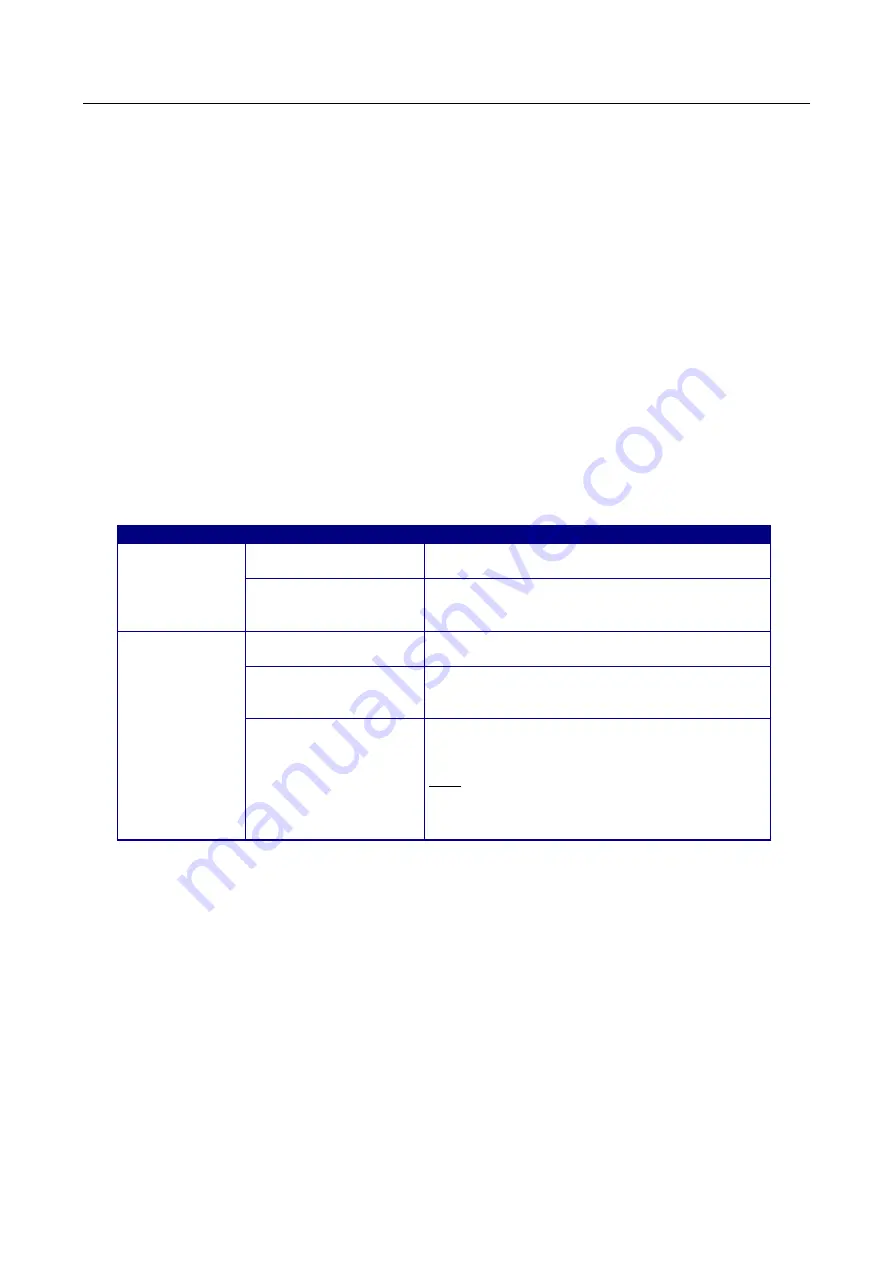
3.13 Special features for system parameters for servo and stepper
motor axes
Please note the system parameters listed below, which must be set accordingly in the
system.dat
system file
using the
mcfg.exe
application.
Operating mode
Parameter/page
Value/meaning
Servo motor
Motor type {mt} /
motion parameters
Servo/operating mode selection
Encoder slits or step
pulses /
motion parameters
Slits/strokes (electronic quadrupling is considered)
Stepper motor
Motor type {mt} /
motion parameters
Stepper/operating mode selection
Encoder slits or step
pulses /
motion parameters
Pulses/steps (no electronic quadrupling)
Filter parameter {kp} /
motor-specific
parameters
0.04 (is set by the system))/ any other value will
lead to instable control behaviour
Note: as of
mcfg.exe
version
2.5.0.45, {kp} can no longer be edited for stepper
motors. You require
rwmos.elf
firmware version
2.5.0.4 or later
What next?
If you have reached this point without any errors, the xPCI-800x controller has been successfully set up and
is ready for use. To complete the installation, you can now execute the following steps in the
mcfg.exe
application:
•
[File] [Dialog Functions][Show Axis Status] to display the current position actual and setpoint values
as well as the axis status information
•
[File] [Dialog Functions][Show Digital Inputs / Status] to display the digital inputs, axis status and
interface status information
•
[File] [Dialog Functions][Edit Digital Outputs] to set or reset the digital outputs
•
[File] [Motion Tools] for manual procedure of the drive axes. In doing this, note that the [Close Loop]
button must also be activated for a stepper motor axis, before the axis can be manually operate
using the [Jog Start], [Jog Stop] or [Jog Back] buttons. This is necessary, as stepper motor axes are
also managed via an internal control algorithm.
Summary of Contents for APCI-8001
Page 4: ......
Page 47: ...CM COMMISSIONING MANUAL 47 5 4 APCI 8001 component mounting diagram ...
Page 48: ...48 CM COMMISSIONING MANUAL 5 5 APCI 8001 component mounting diagram bottom side ...
Page 49: ...CM COMMISSIONING MANUAL 49 5 6 APCI 8008 component mounting diagram ...
Page 50: ...50 CM COMMISSIONING MANUAL 5 7 APCI 8008 component mounting diagram bottom side ...
Page 51: ...CM COMMISSIONING MANUAL 51 5 8 APCI 8008 STP EVAI component mounting diagram ...
Page 52: ...52 CM COMMISSIONING MANUAL 5 9 APCI 8008 STP EVAI component mounting diagram bottom side ...


