


Program edit mode | Program management
5.3
Program management
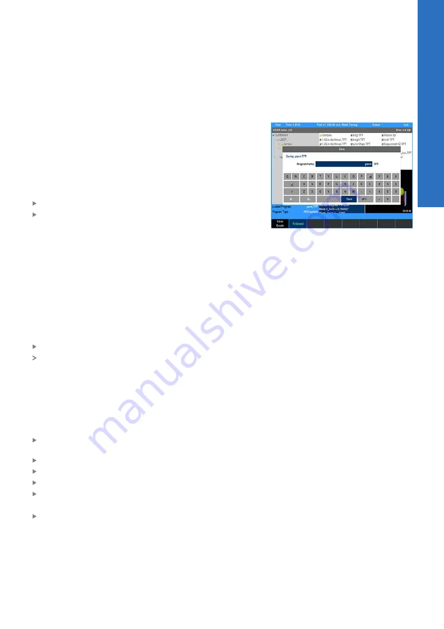
Saving a program
When creating programs, they can be saved within the control's
User folder, on a USB device, or to a network location. A graphic
view of the program is displayed in the Preview Window if it has
been run successfully.
Programs can be organized in the control, on a USB device,in a
network location, or in personalized folders that the operator can
create.
To save the current program for the first time:
Press the
Program Functions
soft key
Press the
Save/Create
soft key
The keyboard should automatically be displayed with the cursor in
the Program Name field. For additional information, see "Keyboard",
Page 30.
Naming a program
Before you can save a program, the control requires it to be named.
Enter the program name using the
Arrow
keys to navigate the
keyboard. Highlight the key to be used (e.g. letter, or number), then
press the enter key to add the selection into the
Program Name
Field. Continue in the same manner until the name is complete.
To add numbers to your program name, press any of the number
keys on the numerical keypad, or from the keyboard display.
Press the
Save/Create
soft key
The control will store the program in the folder that had been
previously selected.
A message will alert you if the program was not saved properly, or
if the name that you’ve chosen already exists.
Back up programs regularly to avoid accidental loss (e.g. USB
device, or to a network location).
Deleting a program
Press the
Change Window
soft key to select the Folder
Contents window
Highlight the desired program
Press the
Function
soft key
Select
Delete
from the popup menu
Press the
Yes
soft key to erase the program
or
Press the
No
soft key to cancel
5
ACU-RITE | TURNPWR | User's Manual | 08/2020
79
Summary of Contents for TURNPWR
Page 1: ...TURNPWR User s Manual English en 08 2020 ...
Page 12: ......
Page 13: ...1 Fundamentals ...
Page 18: ......
Page 19: ...2 Introduction ...
Page 36: ......
Page 37: ...3 Machining fundamentals ...
Page 46: ......
Page 47: ...4 DRO mode ...
Page 58: ......
Page 59: ...5 Program edit mode ...
Page 85: ...6 Tool table ...
Page 94: ......
Page 95: ...7 Programming ...
Page 112: ......
Page 113: ...8 Program steps and cycles ...
Page 144: ......
Page 145: ...9 Demonstration program ...
Page 159: ...10 Calculators ...
Page 172: ......
Page 173: ...11 Setup ...
Page 181: ...12 Machine functions ...
Page 183: ...13 Software update ...
Page 185: ...14 Simulators for Windows PCs ...


