43
KOOLMASTER PP20-VS2 rev.00
KOOLMASTER PP20-VS2
14. TECHNICAL SPECIFICA-
TIONS
Type
KOOLMASTER PP20-
VS2
Main supply Fuse F1
4A, slow-blow
Mains supply/fre-
quency
85-250V, 50/60Hz
0-10V outputs 1-2
0-10Vdc, 30mA
source max.
Precision on 0-10V
outputs
±1 %
14Vdc output
14 VDC ±10%, regu-
lated, 250 mA max.
Variable outputs 1,2
230VAC, 10A Max,
1.5HP (230VAC) /
0.5HP (115VAC)
Alarm contact
150 mA, 24 Vac or
dc max.
Pot + output
3.0V, 20 mA max.
Potentiometer inputs
1-20 K pot., linear
RH input
4-20 mA
Outside RH input
0-2.5V DC
Temperature inputs
1K @ 77 °F (25 °C),
NTC
Relays 1-20
Dry contact
15 A RES, 50/60 Hz
16 FLA @ 120 VAC
(1HP, 746 W)
12 FLA @ 240 VAC
(2HP, 1490 W)
Housing
IP54, plastic casing
Operating temperature
32 to 104°F (0 to
40 °C)
Storage temperature
5 to 122 °F (-15 to
50 °C)
Ambient relative
humidity
max. 95%
Pollution degree
2
Altitude
Up to 2000m
15. MEMORY CARD
Principle of Operation
15.1.
The memory card allows you to upgrade the
firmware or software of your controller with-
out loosing your parameter settings (firmware
and/or software upgrade). The card can also
be used to make a backup of your controller
settings or to copy these settings on another
controller of the same type.
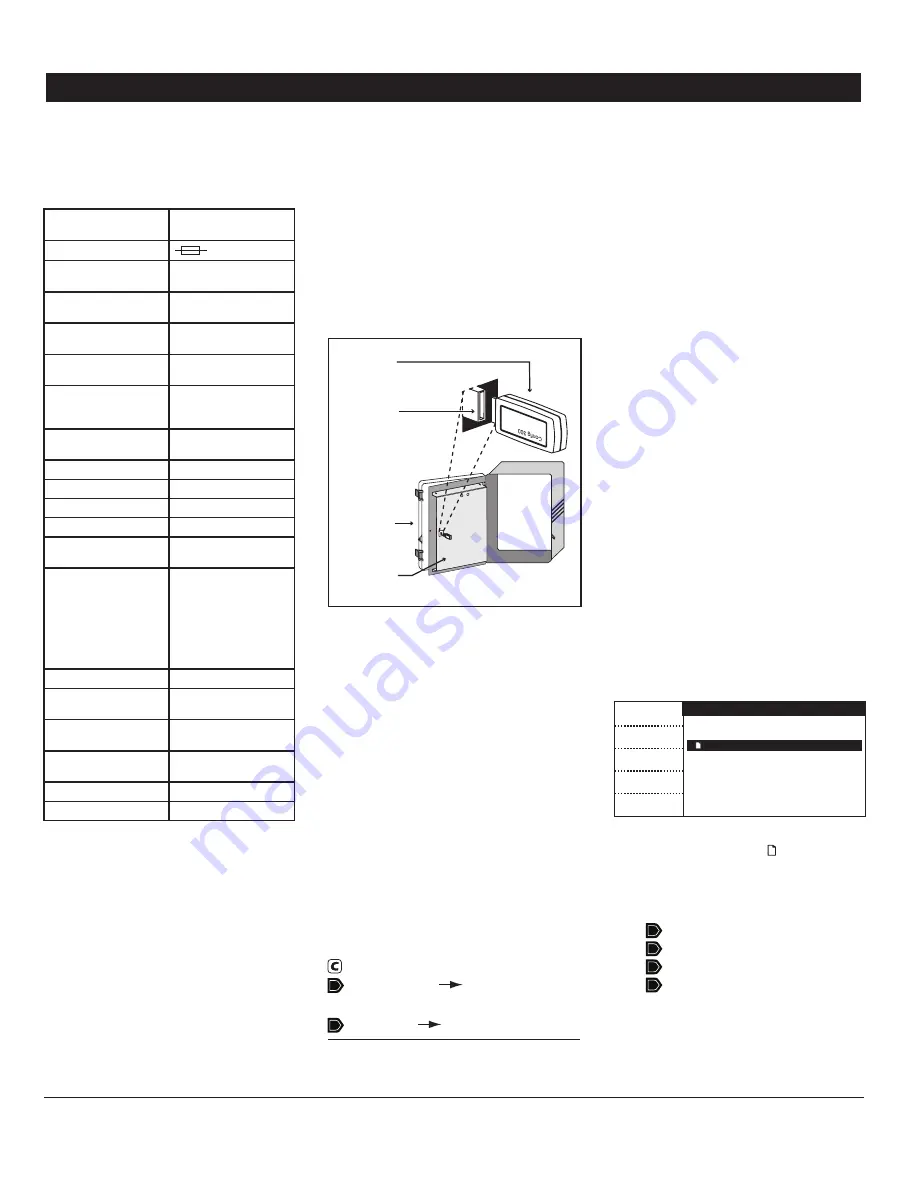
Memory
Card
Connector
Cover
Front Panel
Various kind of files can be stored on the card:
configuration files (*.cfg files) and/or firmware
files (*.fir and *.bin files). Refer to section
14.3 to load or save a configuration file; refer
to section 14.4 to upgrade the firmware.
Accessing the Transfer
15.2.
Menu
Unscrew the screws located on the control-
1.
ler’s front panel then open the panel.
Insert the memory card in the connector
2.
located on the electronic board located on the
back of the front panel (see illustration).
Close the front panel then simultaneously
3.
press the up- and down-arrow keys for 3 sec-
onds to display the transfer menu.
Select the desired transfer menu:
4.
Current Conditions (Main Menu)
Memory Card
Controller
or
Controller
Memory Card
Configuration Transfer
15.3.
Configuration Files (*.cfg)
Configuration files are a set of instructions
that tells the controller what to do. These
files are divided into three parts:
1) Software (screen menus)
2) User data (parameter settings)
3) Potentiometer calibration
You can save your controller’s configuration
on the card or you can install a new configura-
tion into your controller. Note that it is now
possible to install a specific component of the
configuration without affecting the two other
components. For instance, you can upload
new controller software without affecting
your calibration & parameter settings.
Installing a New Configura-
15.3.1.
tion
The following procedure shows how to in-
stall a new configuration in your controller.
You can choose to install the whole new
configuration or to install a specific compo-
nent of it.
Access the transfer menu as explained in
1.
section 14.2 and select the
“Memory card to
controller”
menu.
Memory card to controller
Complete
Software
User Data
Pot. Calib
Exit
File_name.cfg
atm_0_7_30.bin
atm_0_7_30.fir
Select the proper configuration file (*.cfg)
2.
on the main screen. The icon indicates
which files can be used for the transfer.
Press the button that corresponds to the
3.
component(s) you want to install:
Complete (all components)
Software (screen menus)
User data (parameter settings)
Pot. Calib (inlet calib. settings)
Once the transfer is over, press Exit then
4.
remove the memory card from the connector.
Summary of Contents for Koolmaster PP20-VS2
Page 47: ......
Page 48: ...REV 00 M 890 00527 rev 00 ...


