


5-8
Jumper and Connector Locations
Performing a BIOS Recovery
0
Boot Block
0
An interruption during a BIOS flash procedure (e.g. a power outage) can corrupt the BIOS
code, which will cause the system to go into an unbootable state. The BIOS boot block refers
to a special BIOS program that can be used to boot up a system with minimum BIOS
initialization.You need to access and execute the boot block to reboot the computer and
recover the regular BIOS code.
Creating the Crisis Disk
0
NOTE:
NOTE
:
The BIOS crisis recovery disk should be prepared in a computer running the Windows
XP, Vista, or 7 OS.
1.
Prepare a removable USB flash drive.
Note that all data in the USB flash drive will be cleared during the creation of the crisis
disk.
2.
Set up a computer running the Windows XP, Vista, or 7 operating system and plug in the
USB flash drive into an available USB port.
3.
Open the
Notepad
program and create a new file.
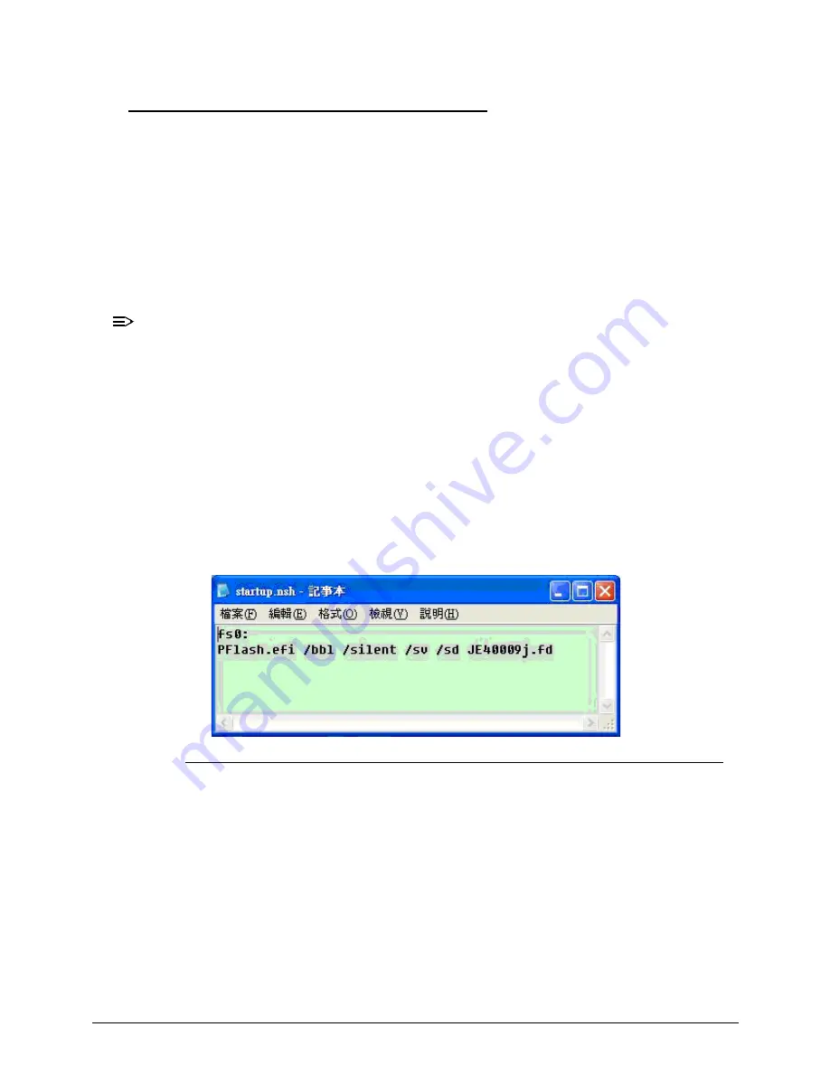
4.
Type
startup.nsh
.
For example, the USB key prompt is
fs0
. The
PFlash.efi
and
BIOS.cap
files are in the
fs0:
root directory
.
Figure 5-5.
Startup.nsh File
5.
Save this file as
startup.nsh
in the USB flash drive’s root directory.
6.
Decompress the Crisis Package Source in the USB flash drive’s root directory.
7.
Eject and reconnect the USB flash drive from the computer, and make sure it contains the
following files:
EFI folder
CrisisRecovery.efi
PFlash.efi
BIOS.cap
Startup.nsh
Summary of Contents for TravelMate P643-V
Page 1: ...TravelMate P643M P643V P643MG SERVICEGUIDE...
Page 10: ...6...
Page 11: ...CHAPTER 1 Hardware Specifications...
Page 14: ...1 4...
Page 53: ...CHAPTER 2 System Utilities...
Page 70: ...2 18 System Utilities...
Page 71: ...CHAPTER 3 Machine Maintenance...
Page 74: ...3 4...
Page 87: ...Machine Maintenance 3 17 6 Pull the HDD from the rubber holder Figure 1 17 HDD Rubber Holder...
Page 91: ...Machine Maintenance 3 21 6 Remove the WLAN module from the slot Figure 1 24 WLAN Module...
Page 117: ...Machine Maintenance 3 47 6 Lift the LCD module from the lower cover Figure 1 69 LCD Module...
Page 167: ...Machine Maintenance 3 97 5 Connect the HDD cable Figure 1 154 HDD Cable...
Page 174: ...3 104 Machine Maintenance...
Page 175: ...CHAPTER 4 Troubleshooting...
Page 205: ...CHAPTER 5 Jumper and Connector Locations...
Page 214: ...5 10 Jumper and Connector Locations...
Page 215: ...CHAPTER 6 FRU List...
Page 229: ...CHAPTER 7 Test Compatible Components...
Page 230: ...7 2 Microsoft Windows 7 Environment Test 7 4...
Page 240: ...7 12 Test Compatible Components...
Page 241: ...CHAPTER 8 Online Support Information...
Page 242: ...8 2...
Page 244: ...8 4 Online Support Information...


