


1-38
Hardware Specifications and Configurations
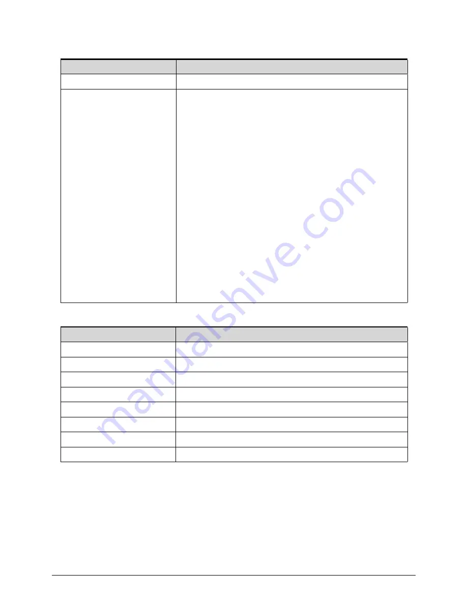
System Power Management
System DMA Specification
Item
Specification
Power management system
ACPI 3.0-compliant
Power global states
G3 Mechanical Off - This off state is entered through a
mechanical means; no electrical current is running through
the circuitry and it can be worked on without damaging the
hardware or endangering service personnel. Except for the
real-time clock, power consumption is zero.
G2/S5 Soft Off - OS initiated shutdown. The computer
consumes a minimal amount of power. No user mode or
system mode code is run. It is not safe to disassemble the
machine in this state.
G1 Sleeping - The computer consumes a small amount of
power, user mode threads are not being executed, and the
system “appears” to be off. It is not safe to disassemble the
machine in this state
G0 Working - The computer dispatches user mode
(application) threads and they execute. It is not safe to
disassemble the machine in this state.
S4 Non-Volatile Sleep - Also known as hibernation state. A
special global system state that allows system context to be
saved and restored (relatively slowly) when power is lost to
the mainboard. It is not safe to disassemble the machine in
this state.
Legacy Mode
Power Management
DMA0
Free
DMA1
Free
DMA2
Free
DMA3
Free
DMA4
Direct memory access controller
DMA5
Free
DMA6
Free
DMA7
Free
Summary of Contents for TravelMate P643-V
Page 1: ...TravelMate P643M P643V P643MG SERVICEGUIDE...
Page 10: ...6...
Page 11: ...CHAPTER 1 Hardware Specifications...
Page 14: ...1 4...
Page 53: ...CHAPTER 2 System Utilities...
Page 70: ...2 18 System Utilities...
Page 71: ...CHAPTER 3 Machine Maintenance...
Page 74: ...3 4...
Page 87: ...Machine Maintenance 3 17 6 Pull the HDD from the rubber holder Figure 1 17 HDD Rubber Holder...
Page 91: ...Machine Maintenance 3 21 6 Remove the WLAN module from the slot Figure 1 24 WLAN Module...
Page 117: ...Machine Maintenance 3 47 6 Lift the LCD module from the lower cover Figure 1 69 LCD Module...
Page 167: ...Machine Maintenance 3 97 5 Connect the HDD cable Figure 1 154 HDD Cable...
Page 174: ...3 104 Machine Maintenance...
Page 175: ...CHAPTER 4 Troubleshooting...
Page 205: ...CHAPTER 5 Jumper and Connector Locations...
Page 214: ...5 10 Jumper and Connector Locations...
Page 215: ...CHAPTER 6 FRU List...
Page 229: ...CHAPTER 7 Test Compatible Components...
Page 230: ...7 2 Microsoft Windows 7 Environment Test 7 4...
Page 240: ...7 12 Test Compatible Components...
Page 241: ...CHAPTER 8 Online Support Information...
Page 242: ...8 2...
Page 244: ...8 4 Online Support Information...


