


4-26
Troubleshooting
POST Codes
0
There are two types of POST codes: Progress Codes and Error Codes. Progress Codes are
designed to show the execution point while booting or executing services. Error Codes are
designed to halt on exceptional (fatal) error conditions.
Component Codes
0
The Component Code is an unsigned integer value that is assigned by the build process. The
following tables describe the various ranges of component codes:
The Component Code is assigned to an individual component (or driver) using the
POSTCODE= option in the DSC file. If the value that follows POSTCODE= is a hexadecimal
or decimal number, in the range 0x00-0xdf, then that code will be used with all POST Codes
associated with that driver.
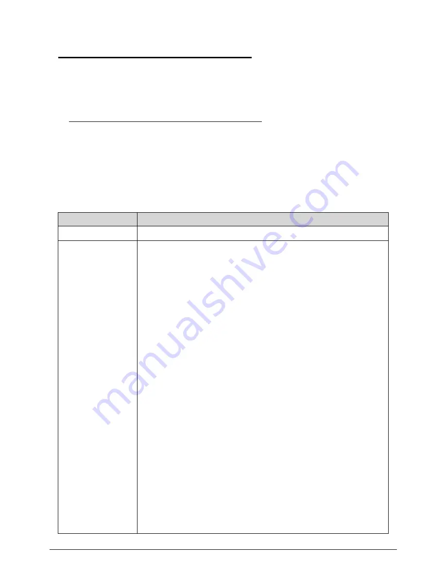
Table 4-4.
Component Codes
Range
Description
0x00-0x1f
OEM Components. These values are reserved for OEM components
0x20-0x9f
These values are reserved for SecureCore Tiano™ core components.
POSTCODE_CC_VARIABLE_SERVICES (0x20)
POSTCODE_CC_KEYBOARD_CONTROLLER (0x21)
POSTCODE_CC_BOOT_MODE (0x22)
POSTCODE_CC_S3_SUPPORT (0x23)
POSTCODE_CC_TCG (0x24)
POSTCODE_CC_HDD_PASSWORD (0x25)
POSTCODE_CC_CPU_IO (0x26)
POSTCODE_CC_BOOT_SCRIPT (0x27)
POSTCODE_CC_STATUS_CODE (0x28)
POSTCODE_CC_DATA_HUB (0x29)
POSTCODE_CC_HII_DATABASE (0x2a)
POSTCODE_CC_RESET (0x2b)
POSTCODE_CC_METRONOME (0x2c)
POSTCODE_CC_INTERRUPT_CONTROLLER (0x2d)
POSTCODE_CC_DIAGNOSTIC_SUMMARY (0x2e)
POSTCODE_CC_SMBIOS (0x2f)
POSTCODE_CC_SMM_COMMUNICATION (0x30)
POSTCODE_CC_SMM_RUNTIME (0x31)
POSTCODE_CC_SMM_SERVICES (0x32)
POSTCODE_CC_FIRMWARE_DEVICE (0x33)
POSTCODE_CC_CAPSULE_SERVICES (0x34)
POSTCODE_CC_MONOTONIC_COUNTER (0x35)
POSTCODE_CC_SMBIOS_EVENT_LOG (0x36)
POSTCODE_CC_RTC (0x37)
POSTCODE_CC_BOOT_MANAGER (0x38)
POSTCODE_CC_VGA (0x39)
Summary of Contents for TravelMate P643-V
Page 1: ...TravelMate P643M P643V P643MG SERVICEGUIDE...
Page 10: ...6...
Page 11: ...CHAPTER 1 Hardware Specifications...
Page 14: ...1 4...
Page 53: ...CHAPTER 2 System Utilities...
Page 70: ...2 18 System Utilities...
Page 71: ...CHAPTER 3 Machine Maintenance...
Page 74: ...3 4...
Page 87: ...Machine Maintenance 3 17 6 Pull the HDD from the rubber holder Figure 1 17 HDD Rubber Holder...
Page 91: ...Machine Maintenance 3 21 6 Remove the WLAN module from the slot Figure 1 24 WLAN Module...
Page 117: ...Machine Maintenance 3 47 6 Lift the LCD module from the lower cover Figure 1 69 LCD Module...
Page 167: ...Machine Maintenance 3 97 5 Connect the HDD cable Figure 1 154 HDD Cable...
Page 174: ...3 104 Machine Maintenance...
Page 175: ...CHAPTER 4 Troubleshooting...
Page 205: ...CHAPTER 5 Jumper and Connector Locations...
Page 214: ...5 10 Jumper and Connector Locations...
Page 215: ...CHAPTER 6 FRU List...
Page 229: ...CHAPTER 7 Test Compatible Components...
Page 230: ...7 2 Microsoft Windows 7 Environment Test 7 4...
Page 240: ...7 12 Test Compatible Components...
Page 241: ...CHAPTER 8 Online Support Information...
Page 242: ...8 2...
Page 244: ...8 4 Online Support Information...


