


Chapter 3
61
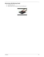
3.
Push forward to detach the touchpad support plate
4.
Remove the two screws to loosn the touchpad support plate
5.
Detach the support plate from here
6.
Disconnect the touchpad cable from the trace board
7.
Detach the trace board from here
Removing the FAN
1.
Disconnect the system fan cable
2.
Remove the two screws to release the system fan from here
3.
Detach the system fan out from the system
Removing the Thermal Module and CPU
1.
Remove the 4 screws to release the CPU thermal module accordingly
2.
Detach the CPU thermal module out from the system
Summary of Contents for TravelMate 4150
Page 9: ...X Table of Contents...
Page 14: ...Chapter 1 5 Mainboard Placement Top View...
Page 15: ...6 Chapter 1 Bottom View...
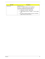
Page 97: ...Chapter 5 88 Top View Jumper and Connector Locations Chapter 5...
Page 98: ...89 Chapter 5 Rear View...
Page 100: ...91 Chapter 5 VGA Board Item Description JP1 VGA Board to MB connector JP2 LCD Connector...
Page 103: ...Chapter 5 94 Hot Swap ODD Board Item Description JP1 Hot Swap JP2 ODD device Connector...
Page 104: ...95 Chapter 5 DVI Board Item Description JP1 DVI Board Connector...
Page 105: ...Chapter 5 96 Clear CMOS...
Page 107: ...98 Chapter 6 Exploded Diagram...
Page 108: ...Chapter 6 99...
Page 126: ...117 Appendix B...


