


Chapter 3
63
2.
Remove the one screw located on each speaker then detach the speakers out from the system
3.
Press down the button to release the PCMCI dummy card then pull the dummy card out from the system
4.
Remove the one screw to loosen the mainobard
5.
Push outward of the side before releasing the mainboard out from the chassis
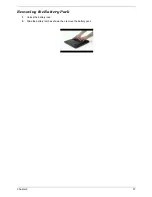
Removing the LCD Panel
1.
Detach the upper LCD rubbers
2.
Detach the LCD mylars from the lower side
Summary of Contents for TravelMate 4150
Page 9: ...X Table of Contents...
Page 14: ...Chapter 1 5 Mainboard Placement Top View...
Page 15: ...6 Chapter 1 Bottom View...
Page 97: ...Chapter 5 88 Top View Jumper and Connector Locations Chapter 5...
Page 98: ...89 Chapter 5 Rear View...
Page 100: ...91 Chapter 5 VGA Board Item Description JP1 VGA Board to MB connector JP2 LCD Connector...
Page 103: ...Chapter 5 94 Hot Swap ODD Board Item Description JP1 Hot Swap JP2 ODD device Connector...
Page 104: ...95 Chapter 5 DVI Board Item Description JP1 DVI Board Connector...
Page 105: ...Chapter 5 96 Clear CMOS...
Page 107: ...98 Chapter 6 Exploded Diagram...
Page 108: ...Chapter 6 99...
Page 126: ...117 Appendix B...


