


Chapter 1
1
Features
This computer was designed with the user in mind. Here are just a few of its many features:
Performance
T
Intel
®
915PM
/
915GM PCI Express chipset
T
Intel
®
Pentium
®
M processor 730/740/750/760/770 (2MB L2 cache, 1.6/1.73/1.86/2.0/2.13 GHz,
533 MHz FSB)
T
CPU Package is uFPGA 478 Package
T
Integrated Intel
®
PRO/Wireless 2200GB network connection (dual-mode 802.11b/g) Wi-Fi
CERTIFIED
TM
solution, supporting Acer SignalUp wireless technology
Memory
T
256MB or 512MB of DDR II 400/533 memory
T
Onboard with two 200-pin +1.8V DDR II soDIMM connector, supporting DDR memories card.
Maximum up gradable to 2GB by two 1GB soDIMM module
T
Support 64MB/128MB VGA memory for NV43M/NV44MV
T
Adjustable 128MB UMA VGA memory share from North Bridge
Display
T
15” XGA TFT LCD, supporting 1024x768 pixel resolution, 16.7 million colours
(for TravelMate 4150 series)
T
15” SXGA TFT LCD, supporting 1400x1050 pixel resolution, 16.7 million colours
(for TravelMate 4650 series)
Graphics
T
nVIDIA
®
GeForce
TM
Go 6600 graphics processing unit (GPU) with 64MB or 128MB of DDR Video
RAM , supporting PCI Express
TM
and Microsoft
®
DirectX
®
9.0 (for TravelMate 4650 series)
T
nVIDIA
®
GeForce
TM
Go 6200 graphics processing unit (GPU) with TurboCache
TM
technology
supporting 128MB video memory supporting PCI Express
TM
and Microsoft
®
DirectX
®
9.0 (for
TravelMate 4150 series)
T
Intel
®
915GM integrated 3D graphics, featuring Intel
®
Graphics Media Accelerator 900 and up to
128MB of video memory, supporting Microsoft
®
DriectX
®
9.0 (for TravelMate 4650/4150 series)
T
Dual independent display support
T
External resolution/refresh rate
T
2048x1536: 85/75/70/66/60 Hz
T
1600x1200: 120/100/85/75/60 Hz
T
1280x1024: 180/160/120/100/90/85/75/70/60 Hz
T
1024x768: 200/160/150/120/100/90/85/75/72/70/60 Hz
T
800x600: 200/160/120/100/90/85/75/72/70/60 Hz
T
MPEG-2/DVD hardware-assisted capability
System Specifications
Chapter 1
Summary of Contents for TravelMate 4150
Page 9: ...X Table of Contents...
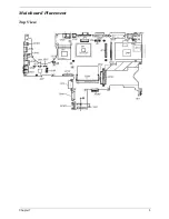
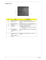
Page 14: ...Chapter 1 5 Mainboard Placement Top View...
Page 15: ...6 Chapter 1 Bottom View...
Page 97: ...Chapter 5 88 Top View Jumper and Connector Locations Chapter 5...
Page 98: ...89 Chapter 5 Rear View...
Page 100: ...91 Chapter 5 VGA Board Item Description JP1 VGA Board to MB connector JP2 LCD Connector...
Page 103: ...Chapter 5 94 Hot Swap ODD Board Item Description JP1 Hot Swap JP2 ODD device Connector...
Page 104: ...95 Chapter 5 DVI Board Item Description JP1 DVI Board Connector...
Page 105: ...Chapter 5 96 Clear CMOS...
Page 107: ...98 Chapter 6 Exploded Diagram...
Page 108: ...Chapter 6 99...
Page 126: ...117 Appendix B...