


Chapter 1
37
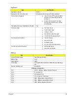
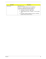
AC Adapter
Item
Specification
Vendor & model name
Delta 3-pin, 19V 3.95A, 64W
Hipro 3-pin, 19V 3.95A, 65W
Lite-on 3-pin, 19V 3.95A, 60W
Details
65W 8-cell Li-ion battery pack
42W 6-cell Li-ion 2
nd
battery pack
T
5-hour battery life on Intel 915GM models
T
3.5-hour charge-in-use
T
2.5-hour rapid charge
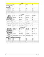
Input Requirements
Maximum input current (A,
@100Vac, full load)
1.8A [email protected]/100Vac and 240 Vac
Nominal frequency (Hz)
47 - 63
Frequency variation range
(Hz)
47 - 63
Nominal voltages (Vrms)
90 - 264
Inrush current
The maximum inrush current will be less than 50A and 100A when
the adapter is connected to 100Vac(60Hz) and 240Vac(50Hz)
respectively.
Efficiency
High efficiency 85% minimum, at 100~240Vac AC input, full load,
warm-up condition.
Output Ratings (CV mode)
DC output voltage
Offers constant voltage 19.0V output source with 150W max output
power capacity.
Noise + Ripple
300mvp-pmax (20MHz bandwidth) for resistor load
Output current
0 A (min.) 3.5A (max.)
Output Ratings (CC mode)
DC output voltage
18.0 ~ 20.0
Constant output
7.9A
Dynamic Output Characteristics
Start-up time
3 sec. (@115 Vac and 230Vac full load)
Hold up time
5ms min. (@115 Vac input, full load)
Over Voltage Protection
(OVP)
25V
Short circuit protection
Output can be shorted without damage, and auto recovery
Electrostatic discharge
(ESD)
15kV (at air discharge)
8kV (at contact discharge)
Dielectric Withstand Voltage
Primary to secondary
4242 Vdc for 1 second-
Leakage current
60uA at 240Vac/60Hz
Regulatory Requirements
1. FCC class B requirements (USA)
2. VDE class B requirements (German)
3. VCCI classII requirements (Japan)
Summary of Contents for TravelMate 4150
Page 9: ...X Table of Contents...
Page 14: ...Chapter 1 5 Mainboard Placement Top View...
Page 15: ...6 Chapter 1 Bottom View...
Page 97: ...Chapter 5 88 Top View Jumper and Connector Locations Chapter 5...
Page 98: ...89 Chapter 5 Rear View...
Page 100: ...91 Chapter 5 VGA Board Item Description JP1 VGA Board to MB connector JP2 LCD Connector...
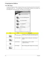
Page 103: ...Chapter 5 94 Hot Swap ODD Board Item Description JP1 Hot Swap JP2 ODD device Connector...
Page 104: ...95 Chapter 5 DVI Board Item Description JP1 DVI Board Connector...
Page 105: ...Chapter 5 96 Clear CMOS...
Page 107: ...98 Chapter 6 Exploded Diagram...
Page 108: ...Chapter 6 99...
Page 126: ...117 Appendix B...


