


24
Chapter 2
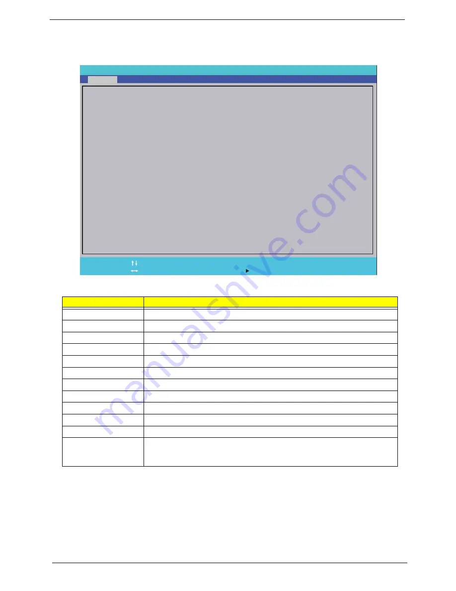
Information
The Information screen displays a summary of your computer hardware information.
NOTE:
The system information is subject to different models.
Parameter
Description
CPU Type
This field shows the CPU type and speed of the system.
CPU Speed
This field shows the speed of the CPU.
HDD Model Name
This field shows the model name of HDD installed on primary IDE master.
HDD Serial Number
This field displays the serial number of HDD installed on primary IDE master.
ATAPI Model Name
This field displays the model name of the installed ODD drive.
System BIOS Version
Displays system BIOS version.
VGA BIOS Version
This field displays the VGA firmware version of the system.
Serial Number
This field displays the serial number of this unit.
Asset Tag Number
This field displays the asset tag number of the system.
Product Name
This field shows product name of the system.
Manufacturer Name
This field displays the manufacturer of this system.
UUID Number
Universally Unique Identifier (UUID) is an identifier standard used in software
construction, standardized by the Open Software Foundation (OSF) as part of
the Distributed Computing Environment (DCE).
P h o e n i x S e c u r e C o r e ( t m ) S e t u p U t i l i t y
F 1
E S C
H e l p
E x i t
S e l e c t I t e m
S e l e c t M e n u
C h a n g e Va l u e s
S e l e c t
S u b M e n u
E n t e r
F 9
F 1 0
S e t u p D e f a u l t
S a v e a n d E x i t
A M D A t h l o n ( t m ) X 2 D u a l C o r e P r o c e s s o r L 3 1 0
1 2 0 0 M H z
W D C W D 3 2 0 0 B E V T - 2 2 Z C T 0
W D - W X 8 0 A 7 9 3 9 8 6 6
v 0 . 3 1 0 2
A T i 0 1 0 . 0 9 4 . 0 0 1 . 0 2 0 . 0 3 3 3 6 8
Z H 6 0 1 2 3 4 5 6 7 Z H 6 A P J X X W W 3
T
A c e r
F F F F F F F F F F F F F F F F F F F F F F F F F F F F F F F F F F
C P U T y p e
C P U S p e e d
H D D M o d e l N a m e :
H D D S e r i a l N u m b e r :
A T A P I M o d e l n a m e :
S y s t e m B I O S V e r s i o n :
V G A B I O S V e r s i o n :
S e r i a l N u m b e r :
A s s e t T a g N u m b e r :
P r o d u c t N a m e :
M a n u f a c t u r e r N a m e :
U U I D :
F 5 / F 6
Main
Boot
Exit
Security
Information
Summary of Contents for Ferrari One 200
Page 2: ...ii PRINTED IN TAIWAN ...
Page 10: ...x Table of Contents ...
Page 13: ...Chapter 1 3 System Block Diagram ...
Page 48: ...38 Chapter 2 ...
Page 60: ...50 Chapter 3 5 Lift the memory card out 6 Repeat steps 4 and 5 for the second memory card ...
Page 63: ...Chapter 3 53 8 Remove the WLAN module ...
Page 74: ...64 Chapter 3 8 Lift the button board away ...
Page 78: ...68 Chapter 3 8 Lift the I O board up by the inner edge and pull away on the angle ...
Page 82: ...72 Chapter 3 7 Lift out the main board from the inside edge ...
Page 84: ...74 Chapter 3 4 Lift the fan away from the main board ...
Page 86: ...76 Chapter 3 2 Lift the RTC battery out of its holder ...
Page 88: ...78 Chapter 3 4 Lift the speaker module out of the lower cover ...
Page 90: ...80 Chapter 3 LCD Bracket Disassembly 2 2 5 4 86 TPK07 001 Step Screw Quantity Part No ...
Page 95: ...Chapter 3 85 4 Lift the LCD panel out of the LCD module ...
Page 100: ...90 Chapter 3 4 Remove the magnet 5 Pull the foil and antennas off the adhesive ...
Page 108: ...98 Chapter 3 2 Press the bezel down around the edges ...
Page 125: ...Chapter 3 115 5 Connect the IO cable to the IO card and main board ...
Page 129: ...Chapter 3 119 2 Press the DIMM module down Replacing the 3G Module 1 Insert the 3G module ...
Page 135: ...Chapter 3 125 Replacing the Dummy Card 1 Insert the dummy card until it clicks into place ...
Page 136: ...126 Chapter 3 ...
Page 156: ...146 Chapter 5 ...
Page 168: ...158 Chapter 6 ...
Page 180: ...170 ...
Page 183: ...173 ...
Page 184: ...174 ...