


148
Chapter 6
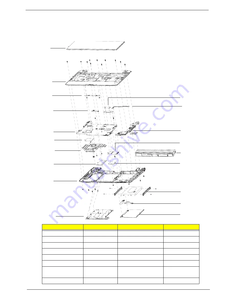
California Exploded Diagrams
Main Assembly
Item
Acer PN
Item
Acer PN
1. Keyboard
KB.I110A.085
11. Bluetooth Module
BH.21100.004
2. Upper Cover
60.FRC07.001
12. DC Power Cable
50.FRC07.002
3. TP board
55.FRC07.002
13. I/O Board
55.FRC07.001
4. IO Cable
TBC
14. 3G Module
LC.21300.011
5. Mainboard
MB.FRB06.001
15. Battery
BT.00603.098
6. Thermal Cable
TBC
16. WLAN Module
NI.23600.047
7. Thermal Module
60.FRC07.008
17. HDD Rails
33.FRC07.003
33.FRC07.004
8. Memory Module
KN.1GB09.013
18. HDD Cable
50.FRC07.003
2
1
15
13
12
5
4
3
6
7
8
9
10
17
18
19
14
16
11
Summary of Contents for Ferrari One 200
Page 2: ...ii PRINTED IN TAIWAN ...
Page 10: ...x Table of Contents ...
Page 13: ...Chapter 1 3 System Block Diagram ...
Page 48: ...38 Chapter 2 ...
Page 60: ...50 Chapter 3 5 Lift the memory card out 6 Repeat steps 4 and 5 for the second memory card ...
Page 63: ...Chapter 3 53 8 Remove the WLAN module ...
Page 74: ...64 Chapter 3 8 Lift the button board away ...
Page 78: ...68 Chapter 3 8 Lift the I O board up by the inner edge and pull away on the angle ...
Page 82: ...72 Chapter 3 7 Lift out the main board from the inside edge ...
Page 84: ...74 Chapter 3 4 Lift the fan away from the main board ...
Page 86: ...76 Chapter 3 2 Lift the RTC battery out of its holder ...
Page 88: ...78 Chapter 3 4 Lift the speaker module out of the lower cover ...
Page 90: ...80 Chapter 3 LCD Bracket Disassembly 2 2 5 4 86 TPK07 001 Step Screw Quantity Part No ...
Page 95: ...Chapter 3 85 4 Lift the LCD panel out of the LCD module ...
Page 100: ...90 Chapter 3 4 Remove the magnet 5 Pull the foil and antennas off the adhesive ...
Page 108: ...98 Chapter 3 2 Press the bezel down around the edges ...
Page 125: ...Chapter 3 115 5 Connect the IO cable to the IO card and main board ...
Page 129: ...Chapter 3 119 2 Press the DIMM module down Replacing the 3G Module 1 Insert the 3G module ...
Page 135: ...Chapter 3 125 Replacing the Dummy Card 1 Insert the dummy card until it clicks into place ...
Page 136: ...126 Chapter 3 ...
Page 156: ...146 Chapter 5 ...
Page 168: ...158 Chapter 6 ...
Page 180: ...170 ...
Page 183: ...173 ...
Page 184: ...174 ...