


128
Chapter 4
Power On Issue
If the system doesn’t power on, perform the following actions one at a time to correct the problem. Do not
replace non-defective FRUs:
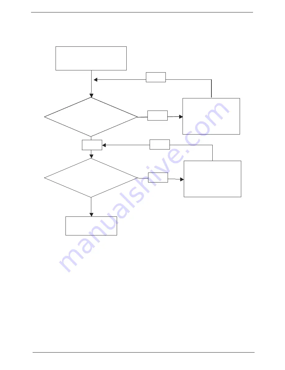
Computer Shuts down Intermittently
If the system powers off at intervals, perform the following actions one at a time to correct the problem.
1.
Check the power cable is properly connected to the computer and the electrical outlet.
2.
Remove any extension cables between the computer and the outlet.
3.
Remove any surge protectors between the computer and the electrical outlet. Plug the computer directly
into a known good electrical outlet.
4.
Remove all external and non-essential hardware connected to the computer that are not necessary to
boot the computer to the failure point.
5.
Remove any recently installed software.
6.
If the Issue is still not resolved, see “Online Support Information” on page 165.
Start
Check
AC/Battery
Power on
Swap AC /Battery
to try
OK
NG
Check
Daughter/B &
FFC Whether
OK
OK
Swap Daughter/B
Re-plug PWR FFC
OK
NG
Swap M/B
Start
Check
AC/Battery
Power on
Swap AC /Battery
to try
OK
NG
Check
Daughter/B &
FFC Whether
OK
OK
Swap Daughter/B
Re-plug PWR FFC
OK
NG
Swap M/B
Start
Summary of Contents for Ferrari One 200
Page 2: ...ii PRINTED IN TAIWAN ...
Page 10: ...x Table of Contents ...
Page 13: ...Chapter 1 3 System Block Diagram ...
Page 48: ...38 Chapter 2 ...
Page 60: ...50 Chapter 3 5 Lift the memory card out 6 Repeat steps 4 and 5 for the second memory card ...
Page 63: ...Chapter 3 53 8 Remove the WLAN module ...
Page 74: ...64 Chapter 3 8 Lift the button board away ...
Page 78: ...68 Chapter 3 8 Lift the I O board up by the inner edge and pull away on the angle ...
Page 82: ...72 Chapter 3 7 Lift out the main board from the inside edge ...
Page 84: ...74 Chapter 3 4 Lift the fan away from the main board ...
Page 86: ...76 Chapter 3 2 Lift the RTC battery out of its holder ...
Page 88: ...78 Chapter 3 4 Lift the speaker module out of the lower cover ...
Page 90: ...80 Chapter 3 LCD Bracket Disassembly 2 2 5 4 86 TPK07 001 Step Screw Quantity Part No ...
Page 95: ...Chapter 3 85 4 Lift the LCD panel out of the LCD module ...
Page 100: ...90 Chapter 3 4 Remove the magnet 5 Pull the foil and antennas off the adhesive ...
Page 108: ...98 Chapter 3 2 Press the bezel down around the edges ...
Page 125: ...Chapter 3 115 5 Connect the IO cable to the IO card and main board ...
Page 129: ...Chapter 3 119 2 Press the DIMM module down Replacing the 3G Module 1 Insert the 3G module ...
Page 135: ...Chapter 3 125 Replacing the Dummy Card 1 Insert the dummy card until it clicks into place ...
Page 136: ...126 Chapter 3 ...
Page 156: ...146 Chapter 5 ...
Page 168: ...158 Chapter 6 ...
Page 180: ...170 ...
Page 183: ...173 ...
Page 184: ...174 ...