


Chapter 1
5
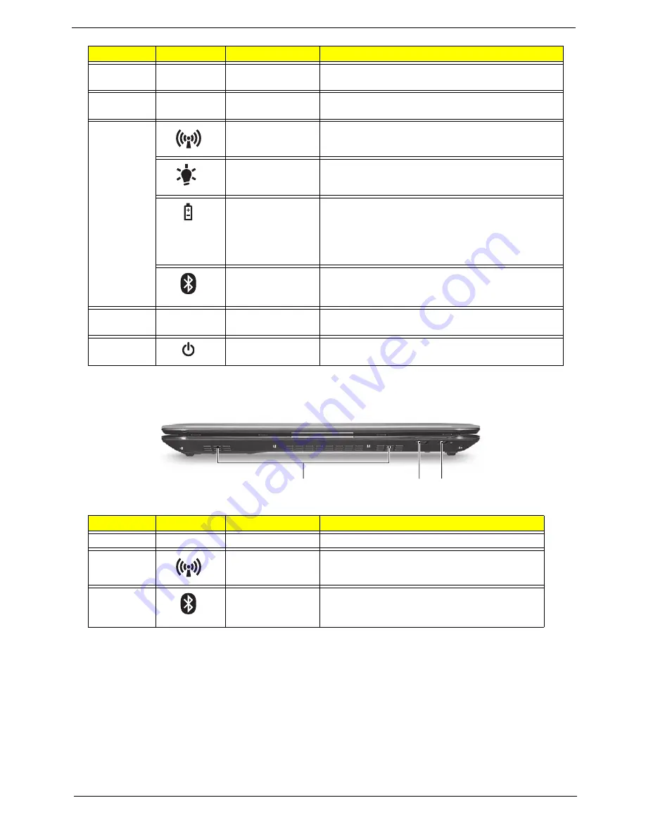
Closed Front View
6
Touchpad
Touch-sensitive pointing device which functions like
a computer mouse.
7
Click buttons (left
and right)
The left and right buttons function like the left and
right mouse buttons.
8
Communication
indicator
Indicates the status of WLAN / 3G communication.
(only for certain models)
Power
Indicates the computer's power status.
Battery
Indicates the computer's battery status.
1. Charging: The light shows amber when the
battery is charging.
2. Fully charged: The light shows blue when in AC
mode.
Bluetooth
communication
indicator
Indicates the status of Bluetooth
communication. (only for certain models)
9
Palmrest
Comfortable support area for your hands when you
use the computer.
10
Power button /
indicator
Turns the computer on and off. / Indicates the
computer's power status.
No.
Icon
Item
Description
1
Speakers
2
Communication
indicator
Indicates the status of WLAN / 3G
communication. (only for certain models)
3
Bluetooth
communication
indicator
Indicates the status of Bluetooth
communication. (only for certain models)
No.
Icon
Item
Description
1
2 3
Summary of Contents for Ferrari One 200
Page 2: ...ii PRINTED IN TAIWAN ...
Page 10: ...x Table of Contents ...
Page 13: ...Chapter 1 3 System Block Diagram ...
Page 48: ...38 Chapter 2 ...
Page 60: ...50 Chapter 3 5 Lift the memory card out 6 Repeat steps 4 and 5 for the second memory card ...
Page 63: ...Chapter 3 53 8 Remove the WLAN module ...
Page 74: ...64 Chapter 3 8 Lift the button board away ...
Page 78: ...68 Chapter 3 8 Lift the I O board up by the inner edge and pull away on the angle ...
Page 82: ...72 Chapter 3 7 Lift out the main board from the inside edge ...
Page 84: ...74 Chapter 3 4 Lift the fan away from the main board ...
Page 86: ...76 Chapter 3 2 Lift the RTC battery out of its holder ...
Page 88: ...78 Chapter 3 4 Lift the speaker module out of the lower cover ...
Page 90: ...80 Chapter 3 LCD Bracket Disassembly 2 2 5 4 86 TPK07 001 Step Screw Quantity Part No ...
Page 95: ...Chapter 3 85 4 Lift the LCD panel out of the LCD module ...
Page 100: ...90 Chapter 3 4 Remove the magnet 5 Pull the foil and antennas off the adhesive ...
Page 108: ...98 Chapter 3 2 Press the bezel down around the edges ...
Page 125: ...Chapter 3 115 5 Connect the IO cable to the IO card and main board ...
Page 129: ...Chapter 3 119 2 Press the DIMM module down Replacing the 3G Module 1 Insert the 3G module ...
Page 135: ...Chapter 3 125 Replacing the Dummy Card 1 Insert the dummy card until it clicks into place ...
Page 136: ...126 Chapter 3 ...
Page 156: ...146 Chapter 5 ...
Page 168: ...158 Chapter 6 ...
Page 180: ...170 ...
Page 183: ...173 ...
Page 184: ...174 ...