


152
Chapter 6
PWR CORD V943B30001218008 DANISH 3P
27.A03V7.006
PWR CORD(ISR)1.8M 3PBLK FZ0I0008-038 27.TATV7.005
PWR CORD V50CB3T3012180QD TW-110V,3P
27.A99V7.002
POWER CORD(SWI)1.8M 3PBLACK FZ010008-011
27.A99V7.004
POWER CORD(IT) 1.8M 3PBLACK FZ010008-008
27.A99V7.005
POWER CORD(S.A) 1.8M 3BLACK FZ010008-006
27.T48V7.001
POWER CORD US 3PIN ROHS
27.TAXV7.001
POWER CORD(EU) 1.8M 3PBLACK FM010008-010
27.TATV7.001
POWER CORD(UK) 1.8M 3PBLACK FP010008-013
27.TATV7.003
POWER CORD BRAZIL IMETRO 3 PIN
27.S0607.001
POWER CORD UK 3PIN
27.A03V7.004
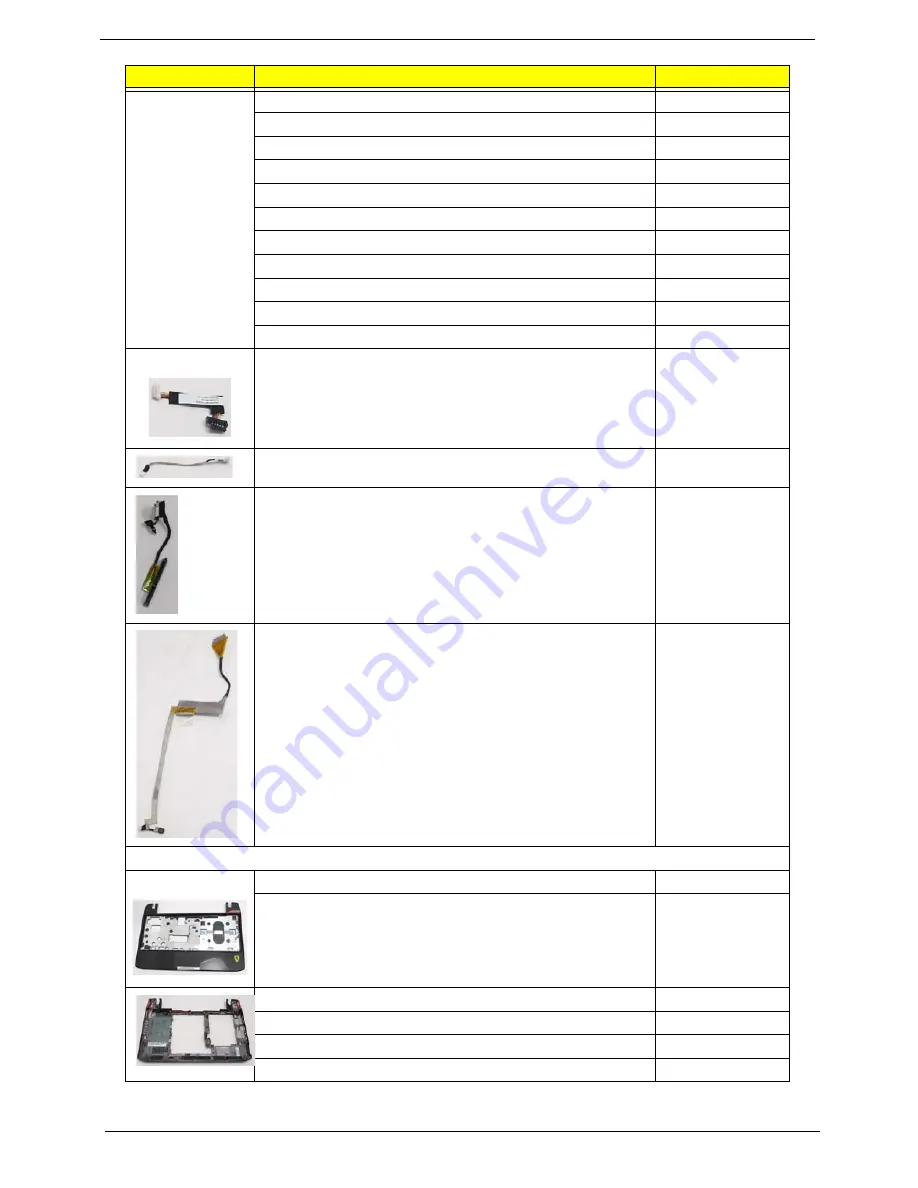
BLUETOOTH CABLE
50.FRC07.001
DC-IN CABLE
50.FRC07.002
HDD CABLE
50.FRC07.003
LCD CABLE
50.FRC07.004
CASE/COVER/BRACKET ASSEMBLY
UPPER CASE ASSY BLACK FOR BT W/TP
60.FRC07.001
UPPER CASE ASSY BLACK FOR NON BT W/TP
60.FRC07.002
LOWER CASE ASSY BLACK FOR 3G/BT
60.FRB07.001
LOWER CASE ASSY BLACK FOR 3G, NON BT
60.FRB07.002
LOWER CASE ASSY BLACK FOR WF BT
60.FRC07.003
LOWER CASE ASSY BLACK FOR WF , NONBT
60.FRC07.004
CATEGORY
PARTNAME
ACERPARTNO.
Summary of Contents for Ferrari One 200
Page 2: ...ii PRINTED IN TAIWAN ...
Page 10: ...x Table of Contents ...
Page 13: ...Chapter 1 3 System Block Diagram ...
Page 48: ...38 Chapter 2 ...
Page 60: ...50 Chapter 3 5 Lift the memory card out 6 Repeat steps 4 and 5 for the second memory card ...
Page 63: ...Chapter 3 53 8 Remove the WLAN module ...
Page 74: ...64 Chapter 3 8 Lift the button board away ...
Page 78: ...68 Chapter 3 8 Lift the I O board up by the inner edge and pull away on the angle ...
Page 82: ...72 Chapter 3 7 Lift out the main board from the inside edge ...
Page 84: ...74 Chapter 3 4 Lift the fan away from the main board ...
Page 86: ...76 Chapter 3 2 Lift the RTC battery out of its holder ...
Page 88: ...78 Chapter 3 4 Lift the speaker module out of the lower cover ...
Page 90: ...80 Chapter 3 LCD Bracket Disassembly 2 2 5 4 86 TPK07 001 Step Screw Quantity Part No ...
Page 95: ...Chapter 3 85 4 Lift the LCD panel out of the LCD module ...
Page 100: ...90 Chapter 3 4 Remove the magnet 5 Pull the foil and antennas off the adhesive ...
Page 108: ...98 Chapter 3 2 Press the bezel down around the edges ...
Page 125: ...Chapter 3 115 5 Connect the IO cable to the IO card and main board ...
Page 129: ...Chapter 3 119 2 Press the DIMM module down Replacing the 3G Module 1 Insert the 3G module ...
Page 135: ...Chapter 3 125 Replacing the Dummy Card 1 Insert the dummy card until it clicks into place ...
Page 136: ...126 Chapter 3 ...
Page 156: ...146 Chapter 5 ...
Page 168: ...158 Chapter 6 ...
Page 180: ...170 ...
Page 183: ...173 ...
Page 184: ...174 ...