


Chapter 2
33
1.
Use the
↑
and
↓
keys to highlight the Set Supervisor Password parameter and press the
Enter
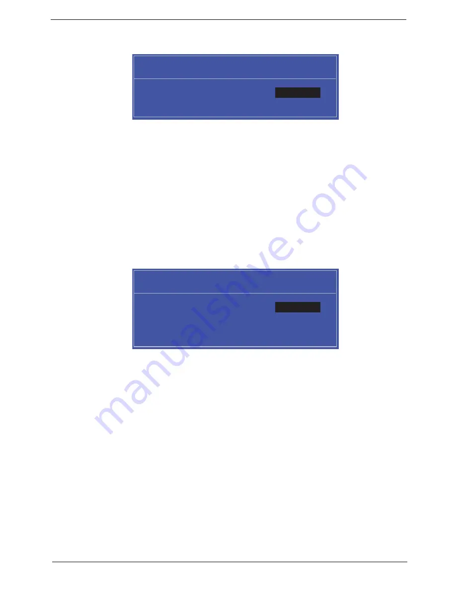
key. The
Set Supervisor Password box appears:
2.
Type a password in the “Enter New Password” field. The password length can not exceeds 8
alphanumeric characters (A-Z, a-z, 0-9, not case sensitive). Retype the password in the “Confirm New
Password” field.
IMPORTANT:
Be very careful when typing your password because the characters do not appear on the screen.
3.
Press
Enter
.
After setting the password, the computer sets the User Password parameter to “Set”.
4.
If desired, you can opt to enable the Password on boot parameter.
5.
When you are done, press F10 to save the changes and exit the BIOS Setup Utility.
Removing a Password
Follow these steps:
1.
Use the
↑
and
↓
keys to highlight the Set Supervisor Password parameter and press the
Enter
key. The
Set Password box appears:
2.
Type the current password in the Enter Current Password field and press
Enter
.
3.
Press
Enter
twice
without
typing anything in the Enter New Password and Confirm New Password fields.
The computer then sets the Supervisor Password parameter to “Clear”.
4.
When you have changed the settings, press
u
to save the changes and exit the BIOS Setup Utility.
S e t S u p e r v i s o r P a s s w o r d
E n t e r N e w P a s s w o r d [ ]
[ ]
C o n f i r m N e w P a s s w o r d [ ]
S e t S u p e r v i s o r P a s s w o r d
E n t e r C u r r e n t P a s s w o r d [ ]
[ ]
E n t e r N e w P a s s w o r d [ ]
C o n f i r m N e w P a s s w o r d [ ]
[ ]
Summary of Contents for Aspire one 521 Series
Page 6: ...VI ...
Page 10: ...X Table of Contents ...
Page 49: ...Chapter 2 39 5 Flash is complete when the message Flash programming complete displays ...
Page 67: ...Chapter 3 57 5 Pull the WLAN module out and away ...
Page 69: ...Chapter 3 59 5 Pull the 3Gmodule out and away ...
Page 73: ...Chapter 3 63 4 Detach the keyboard FPC a Unlock the FPC b Pull the keyboard away a b ...
Page 86: ...76 Chapter 3 4 Lift the speakers clear of the lower cover ...
Page 101: ...Chapter 3 91 3 Secure the speaker cable using a strip of adhesive tape ...
Page 105: ...Chapter 3 95 4 Place the LVDS cable in the hinge channel as shown ...
Page 120: ...110 Chapter 3 ...
Page 136: ...126 Chapter 4 ...
Page 137: ...Chapter 5 127 Jumper and Connector Locations Mainboard Top View Chapter 5 ...
Page 138: ...128 Chapter 5 Mainboard Bottom View CN12 HDMI ...
Page 140: ...130 Chapter 5 ...
Page 142: ...132 Chapter 6 Main Assembly Item Description Part Number 1 2 3 4 5 6 ...
Page 149: ...Appendix A 139 Model Definition and Configuration Appendix A ...
Page 172: ...162 Appendix B ...
Page 174: ...164 ...
Page 177: ...167 Index ...