


32
Chapter 2
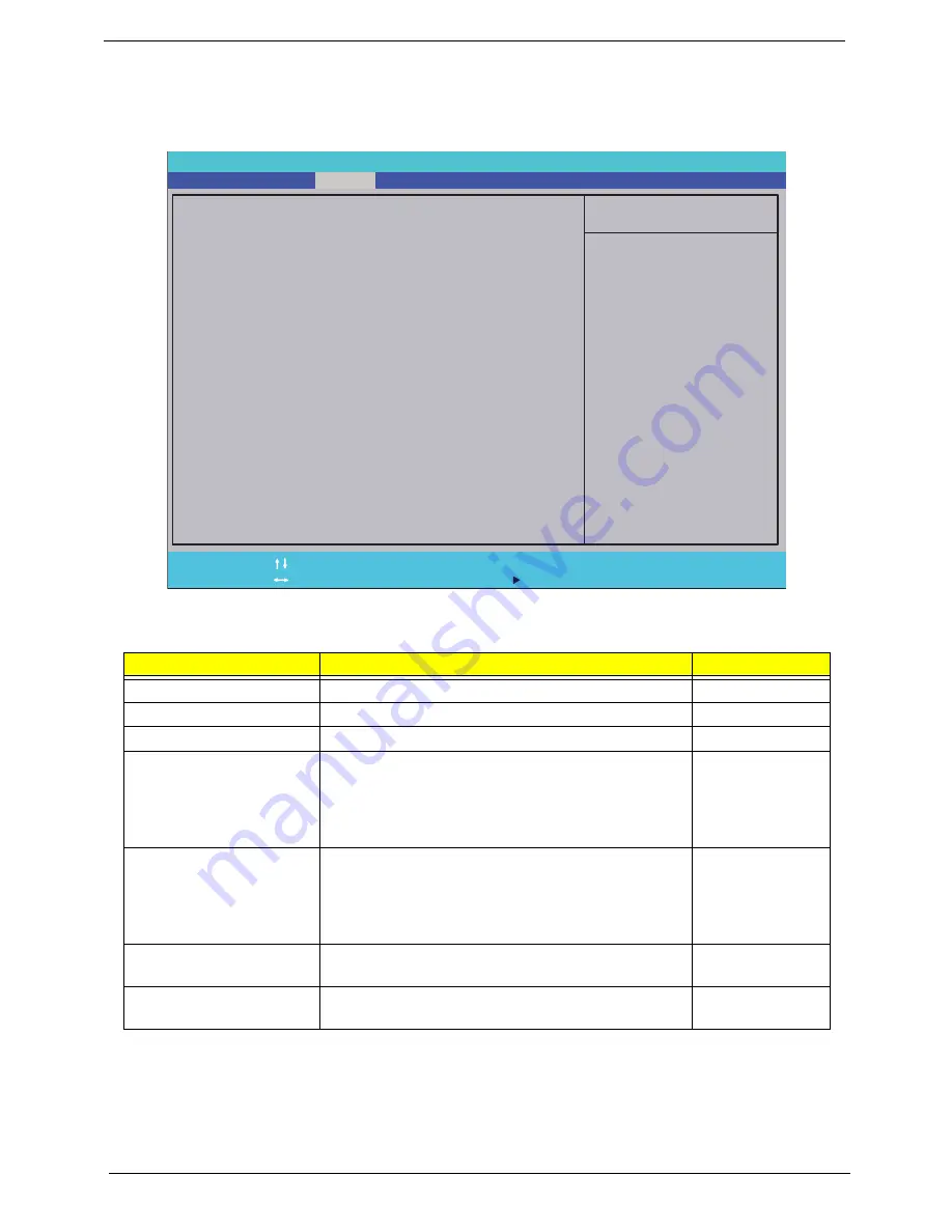
Security
The Security screen contains parameters that help safeguard and protect your computer from unauthorized
use.
The table below describes the parameters in this screen. Settings in
boldface
are the default and suggested
parameter settings.
NOTE:
When you are prompted to enter a password, you have three tries before the system halts. Don’t forget
the password. If you forget the password, you may have to reset the computer.
Setting a Password
Follow these steps as you set the user or the supervisor password:
Parameter
Description
Option
Supervisor Password Is
Shows the setting of the Supervisor password
Clear
or Set
User Password Is
Shows the setting of the user password.
Clear
or Set
HDD Password Is
Shows the setting of the HDD password
Clear
or Set
Set Supervisor Password
Press Enter to set the supervisor password. When
set, this password protects the BIOS Setup Utility
from unauthorized access. The user can not either
enter the Setup menu nor change the value of
parameters.
Set User Password
Press Enter to set the user password. When user
password is set, this password protects the BIOS
Setup Utility from unauthorized access. The user can
enter Setup menu only and does not have right to
change the value of parameters.
Set HDD Password
Press Enter to set the HDD password. When set this
protects the HDD from unauthorized access.
Password on boot
Defines whether a password is required or not for the
system to boot completely.
Disabled
or
Enabled
I t e m S p e c i f i c H e l p
S u p e r v i s o r P a s s w o r d
c o n t r o l s a c c e s s t o t h e
s e t u p u t i l i t y.
F 1
E S C
H e l p
E x i t
S e l e c t I t e m
S e l e c t M e n u
C h a n g e Va l u e s
S e l e c t
S u b M e n u
E n te r
F 9
F 10
S e t u p D e f a u l t
S a v e a n d E x i t
C l e a r
C l e a r
C l e a r
[ E n t e r ]
[ E n t e r ]
[ E n t e r ]
[ D i s a b l e d ]
C l e a r
C l e a r
C l e a r
[ E n t e r ]
[ E n t e r ]
[ E n t e r ]
[ D i s a b l e d ]
S u p e r v i s o r P a s s w o r d I s :
U s e r P a s s w o r d I s :
H D D P a s s w o r d I s :
S e t S u p e r v i s o r P a s s w o r d
S e t U s e r P a s s w o r d
S e t H D D P a s s w o r d
P a s s w o r d o n b o o t :
S u p e r v i s o r P a s s w o r d I s :
U s e r P a s s w o r d I s :
H D D P a s s w o r d I s :
S e t S u p e r v i s o r P a s s w o r d
S e t U s e r P a s s w o r d
S e t H D D P a s s w o r d
P a s s w o r d o n b o o t :
F 5 / F 6
P h o e n i x S e c u r e C o r e ( t m ) S e t u p U t i l i t y
Information
Main
Boot
Exit
Security
Summary of Contents for Aspire one 521 Series
Page 6: ...VI ...
Page 10: ...X Table of Contents ...
Page 49: ...Chapter 2 39 5 Flash is complete when the message Flash programming complete displays ...
Page 67: ...Chapter 3 57 5 Pull the WLAN module out and away ...
Page 69: ...Chapter 3 59 5 Pull the 3Gmodule out and away ...
Page 73: ...Chapter 3 63 4 Detach the keyboard FPC a Unlock the FPC b Pull the keyboard away a b ...
Page 86: ...76 Chapter 3 4 Lift the speakers clear of the lower cover ...
Page 101: ...Chapter 3 91 3 Secure the speaker cable using a strip of adhesive tape ...
Page 105: ...Chapter 3 95 4 Place the LVDS cable in the hinge channel as shown ...
Page 120: ...110 Chapter 3 ...
Page 136: ...126 Chapter 4 ...
Page 137: ...Chapter 5 127 Jumper and Connector Locations Mainboard Top View Chapter 5 ...
Page 138: ...128 Chapter 5 Mainboard Bottom View CN12 HDMI ...
Page 140: ...130 Chapter 5 ...
Page 142: ...132 Chapter 6 Main Assembly Item Description Part Number 1 2 3 4 5 6 ...
Page 149: ...Appendix A 139 Model Definition and Configuration Appendix A ...
Page 172: ...162 Appendix B ...
Page 174: ...164 ...
Page 177: ...167 Index ...