


Chapter 4
119
9.
Restore system and file settings from a known good date using
System
Restore
.
If the issue is not fixed, repeat the preceding steps and select an earlier time and date.
10.
Reinstall the Operating System.
11.
If the Issue is still not resolved, see “Online Support Information” on page 163.
Internal Microphone Failure
If the internal
Microphone
fails, perform the following actions one at a time to correct the problem. Do not
replace non-defective FRUs:
Microphone Problems
If internal or external
Microphones
do no operate correctly, perform the following actions one at a time to
correct the problem.
1.
Check that the microphone is enabled. Navigate to
Start
´
Control
Panel
´
Hardware
and
Sound
´
Sound
and select the
Recording
tab.
2.
Right-click on the
Recording
tab and select
Show
Disabled
Devices
(clear by default).
3.
The microphone appears on the
Recording
tab.
4.
Right-click on the microphone and select
Enable
.
5.
Select the microphone then click
Properties
. Select the
Levels
tab.
6.
Increase the volume to the maximum setting and click
OK
.
7.
Test the microphone hardware:
a.
Select the microphone and click
Configure
.
b.
Select
Set up microphone
.
c.
Select the microphone type from the list and click
Next
.
d.
Follow the onscreen prompts to complete the test.
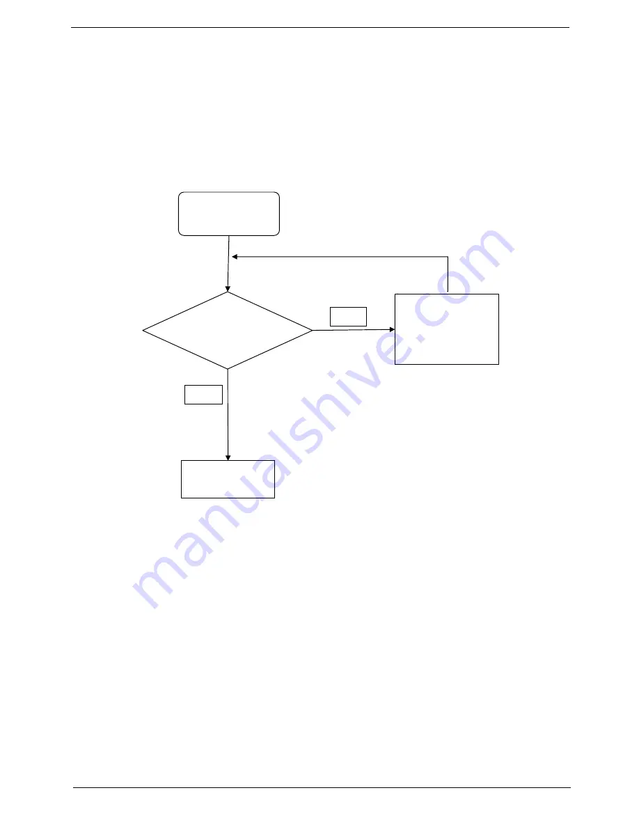
Start
Check M/B Mic.
cable
Re-assemble the
MIC cable to M/B
NG
Swap M/B
OK
Summary of Contents for Aspire one 521 Series
Page 6: ...VI ...
Page 10: ...X Table of Contents ...
Page 49: ...Chapter 2 39 5 Flash is complete when the message Flash programming complete displays ...
Page 67: ...Chapter 3 57 5 Pull the WLAN module out and away ...
Page 69: ...Chapter 3 59 5 Pull the 3Gmodule out and away ...
Page 73: ...Chapter 3 63 4 Detach the keyboard FPC a Unlock the FPC b Pull the keyboard away a b ...
Page 86: ...76 Chapter 3 4 Lift the speakers clear of the lower cover ...
Page 101: ...Chapter 3 91 3 Secure the speaker cable using a strip of adhesive tape ...
Page 105: ...Chapter 3 95 4 Place the LVDS cable in the hinge channel as shown ...
Page 120: ...110 Chapter 3 ...
Page 136: ...126 Chapter 4 ...
Page 137: ...Chapter 5 127 Jumper and Connector Locations Mainboard Top View Chapter 5 ...
Page 138: ...128 Chapter 5 Mainboard Bottom View CN12 HDMI ...
Page 140: ...130 Chapter 5 ...
Page 142: ...132 Chapter 6 Main Assembly Item Description Part Number 1 2 3 4 5 6 ...
Page 149: ...Appendix A 139 Model Definition and Configuration Appendix A ...
Page 172: ...162 Appendix B ...
Page 174: ...164 ...
Page 177: ...167 Index ...