


Chapter 1
11
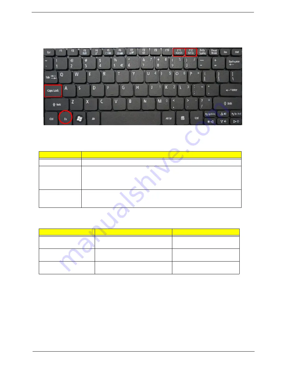
Using the Keyboard
Your computer has a close-to-full-sized keyboard and an embedded numeric keypad, separate cursor, lock,
function and special keys.
Lock Keys and embedded numeric keypad
The keyboard has three lock keys which you can toggle on and off.
The embedded numeric keypad functions like a desktop numeric keypad. It is indicated by small characters
located on the upper right corner of the keycaps. To simplify the keyboard legend, cursor-control key symbols
are not printed on the keys.
Lock key
Description
Caps Lock
When Caps Lock is on, all alphabetic characters typed are in uppercase.
Num Lock
When Num Lock is on, the embedded keypad is in numeric mode. The keys
function as a calculator (complete with the arithmetic ope, -, *, and /). Use
this mode when you need to do a lot of numeric data entry. A better solution
would be to connect an external keypad.
Scroll Lock
<Fn> +
<F12>
When Scroll Lock is on, the screen moves one line up or down when you press
the up or down arrow keys respectively. Scroll Lock does not work with some
applications.
Desired access
Num Lock on
Num Lock off
Number keys on
embedded keypad
Type numbers in a normal manner.
Cursor-control keys on
embedded keypad
Hold <Shift> while using cursor-
control keys.
Hold <Fn> while using cursor-
control keys.
Main keyboard keys
Hold
<Fn>
while typing letters on
embedded keypad.
Type the letters in a normal
manner.
Summary of Contents for Aspire one 521 Series
Page 6: ...VI ...
Page 10: ...X Table of Contents ...
Page 49: ...Chapter 2 39 5 Flash is complete when the message Flash programming complete displays ...
Page 67: ...Chapter 3 57 5 Pull the WLAN module out and away ...
Page 69: ...Chapter 3 59 5 Pull the 3Gmodule out and away ...
Page 73: ...Chapter 3 63 4 Detach the keyboard FPC a Unlock the FPC b Pull the keyboard away a b ...
Page 86: ...76 Chapter 3 4 Lift the speakers clear of the lower cover ...
Page 101: ...Chapter 3 91 3 Secure the speaker cable using a strip of adhesive tape ...
Page 105: ...Chapter 3 95 4 Place the LVDS cable in the hinge channel as shown ...
Page 120: ...110 Chapter 3 ...
Page 136: ...126 Chapter 4 ...
Page 137: ...Chapter 5 127 Jumper and Connector Locations Mainboard Top View Chapter 5 ...
Page 138: ...128 Chapter 5 Mainboard Bottom View CN12 HDMI ...
Page 140: ...130 Chapter 5 ...
Page 142: ...132 Chapter 6 Main Assembly Item Description Part Number 1 2 3 4 5 6 ...
Page 149: ...Appendix A 139 Model Definition and Configuration Appendix A ...
Page 172: ...162 Appendix B ...
Page 174: ...164 ...
Page 177: ...167 Index ...