


Chapter 4
113
No Display Issue
If the
Display
doesn’t work, perform the following actions one at a time to correct the problem. Do not replace
non-defective FRUs:
No POST or Video
If the POST or video doesn’t display, perform the following actions one at a time to correct the problem.
1.
Make sure that the internal display is selected. On this notebook model, switching between the internal
display and the external display is done by pressing
Fn+F5
. Reference Product pages for specific model
procedures.
2.
Make sure the computer has power by checking at least one of the following occurs:
•
Fans start up
•
Status LEDs light up
If there is no power, see “Power On Issue” on page 112.
3.
Drain any stored power by removing the power cable and battery and holding down the power button for
10 seconds. Reconnect the power and reboot the computer.
4.
Connect an external monitor to the computer and switch between the internal display and the external
display is by pressing
Fn+F5
(on this model).
If the POST or video appears on the external display, see “LCD Failure” on page 115.
5.
Disconnect power and all external devices including port replicators or docking stations. Remove any
memory cards and CD/DVD discs. Restart the computer.
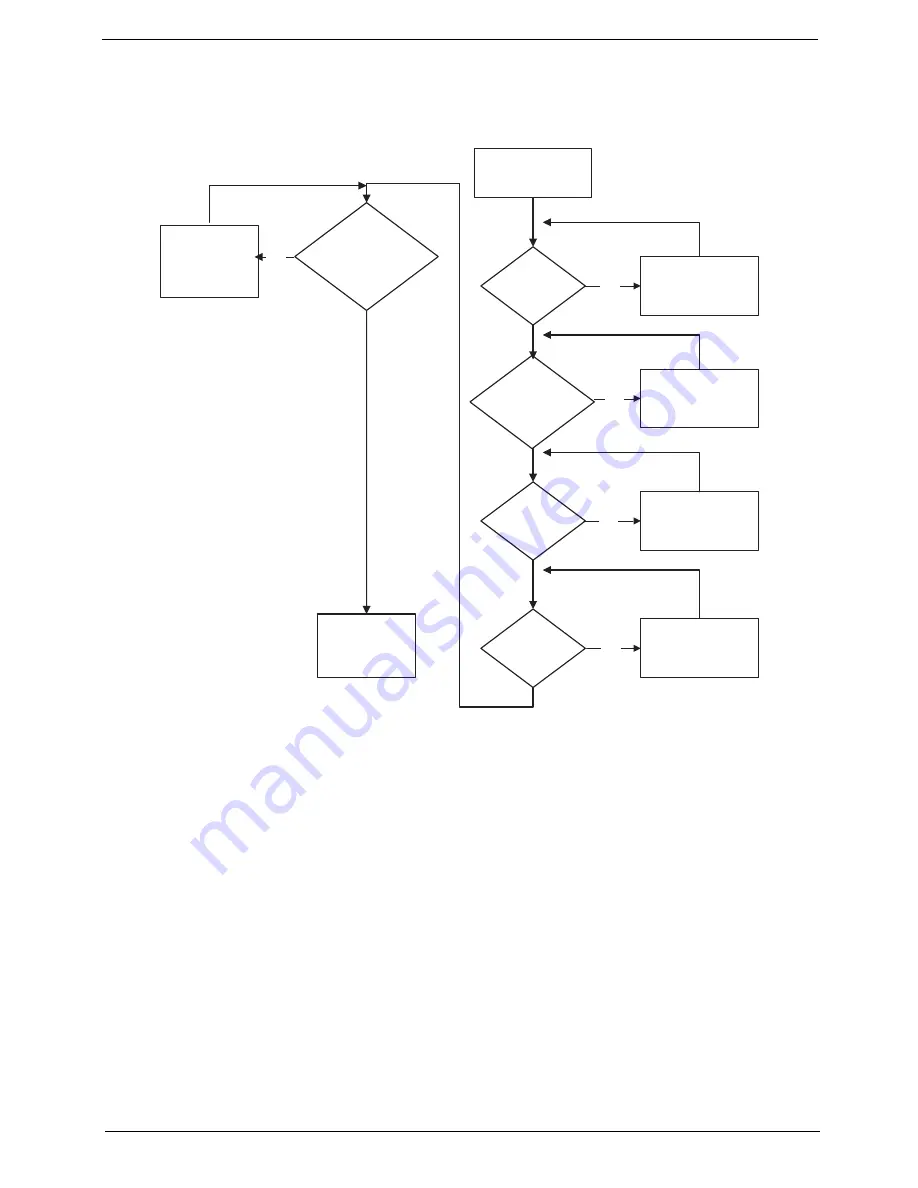
START
Power On ?
No
Go to No Power
troubleshooting
step
Replace external
DDRAM module
Remove and
replace thermal
module
Replace the
main board
Reconnect
SDRAM Module
LCD Module OK?
Replace LCD
Panel and
Cable
Ext. DDRAM module
connected properly?
Ext. DDRAM
module functional?
CPU Thermal
Module properly
connected?
No
No
No
No
Summary of Contents for Aspire one 521 Series
Page 6: ...VI ...
Page 10: ...X Table of Contents ...
Page 49: ...Chapter 2 39 5 Flash is complete when the message Flash programming complete displays ...
Page 67: ...Chapter 3 57 5 Pull the WLAN module out and away ...
Page 69: ...Chapter 3 59 5 Pull the 3Gmodule out and away ...
Page 73: ...Chapter 3 63 4 Detach the keyboard FPC a Unlock the FPC b Pull the keyboard away a b ...
Page 86: ...76 Chapter 3 4 Lift the speakers clear of the lower cover ...
Page 101: ...Chapter 3 91 3 Secure the speaker cable using a strip of adhesive tape ...
Page 105: ...Chapter 3 95 4 Place the LVDS cable in the hinge channel as shown ...
Page 120: ...110 Chapter 3 ...
Page 136: ...126 Chapter 4 ...
Page 137: ...Chapter 5 127 Jumper and Connector Locations Mainboard Top View Chapter 5 ...
Page 138: ...128 Chapter 5 Mainboard Bottom View CN12 HDMI ...
Page 140: ...130 Chapter 5 ...
Page 142: ...132 Chapter 6 Main Assembly Item Description Part Number 1 2 3 4 5 6 ...
Page 149: ...Appendix A 139 Model Definition and Configuration Appendix A ...
Page 172: ...162 Appendix B ...
Page 174: ...164 ...
Page 177: ...167 Index ...