


54
Chapter 3
General Information
Pre-disassembly Instructions
Before proceeding with the disassembly procedure, make sure that you do the following:
1.
Turn off the power to the system and all peripherals.
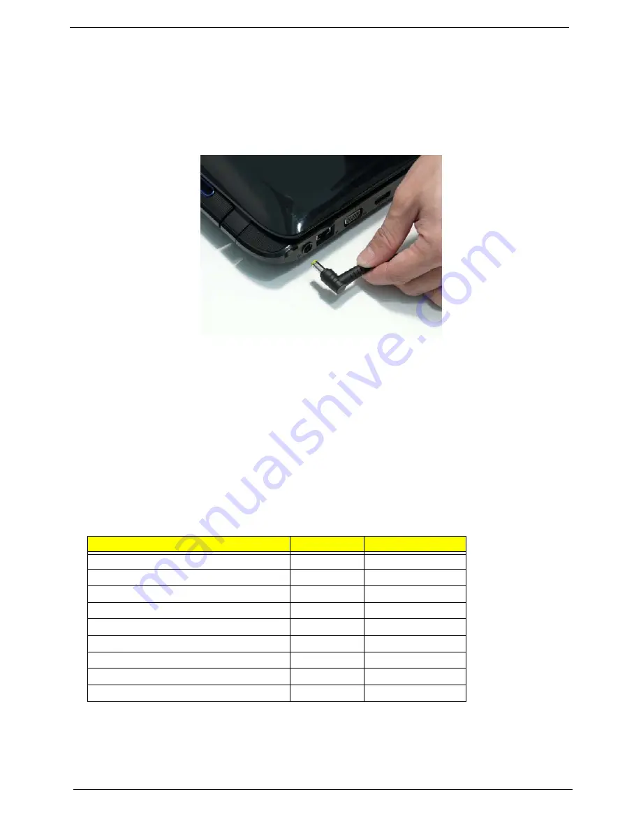
2.
Unplug the AC adapter and all power and signal cables from the system.
3.
Place the system on a flat, stable surface.
4.
Remove the battery pack.
Disassembly Process
The disassembly process is divided into the following stages:
•
External module disassembly
•
Main unit disassembly
•
LCD module disassembly
The flowcharts provided in the succeeding disassembly sections illustrate the entire disassembly sequence.
Observe the order of the sequence to avoid damage to any of the hardware components. For example, if you
want to remove the main board, you must first remove the keyboard, then disassemble the inside assembly
frame in that order.
Main Screw List
Screw
Quantity
Part Number
SCREW M3*0.5+3.5I
86.A03V7.006
SCREW M2.0*6-I(ANTI-LOOSE)
86.N1407.001
SCREW M2.5*2-I (NI,NYLOK)
86.TDY07.001
SCREW M2.5*4-I(BNI)
86.N1407.003
SCREW M2.0*3.0-I IRON
86.S0207.001
SCREW M2.5*4.0-I(NI)(NYLOK)
86.D01V7.001
SCREW M2.5*6.5-I(BZN(NYLOK-RED)
86.ARE07.001
SCREW M2.5*5.0-I(NI)
86.ARE07.004
SCREW M3*0.5+3.5I
86.TDY07.003
Summary of Contents for Aspire 8935G
Page 6: ...VI ...
Page 44: ...34 Chapter 1 ...
Page 62: ...52 Chapter 2 ...
Page 78: ...68 Chapter 3 4 Remove the TV Tuner as shown ...
Page 80: ...70 Chapter 3 4 Detach the WLAN Module from the WLAN socket ...
Page 97: ...Chapter 3 87 5 Lift the board clear of the Upper Cover ...
Page 100: ...90 Chapter 3 5 Lift the Media Board clear of the Upper Cover ...
Page 106: ...96 Chapter 3 8 Lift the board clear of the Upper Cover ...
Page 109: ...Chapter 3 99 5 Remove the Bluetooth Board from the Lower Cover ...
Page 118: ...108 Chapter 3 4 Using both hands lift the Subwoofer clear of the Lower Cover ...
Page 155: ...Chapter 3 145 3 Press down around the perimeter of the bezel to secure it in place ...
Page 173: ...Chapter 3 163 4 Connect the Bluetooth cable to the Mainboard ...
Page 184: ...174 Chapter 3 4 Connect the Volume Control FFC to the Media Board and close the locking latch ...
Page 202: ...192 Chapter 3 2 Tighten the seven captive screws in the Lower Door ...
Page 204: ...194 Chapter 3 ...
Page 239: ...Chapter 6 229 ...
Page 316: ...306 Appendix C ...
Page 320: ...310 ...