


150
Chapter 3
Replacing the Graphics Card Heatsink
IMPORTANT:
Apply a suitable thermal grease and ensure all heat pads are in place before replacing the Thermal
Module.
The following thermal grease types are approved for use:
•
Silmore GP50
•
Honeywell PCM45F-SP
•
ShinEtsu 7762
The following thermal pads are approved for use:
•
Eapus XR-PE
1.
Remove all traces of thermal grease from the CPU using a lint-free cloth or cotton swab and Isopropyl Alcohol,
Acetone, or other approved cleaning agent.
2.
Apply a small amount of thermal grease to the centre of the CPU—there is no need to spread the grease
manually, the force used during the installation of the Thermal Module is sufficient.
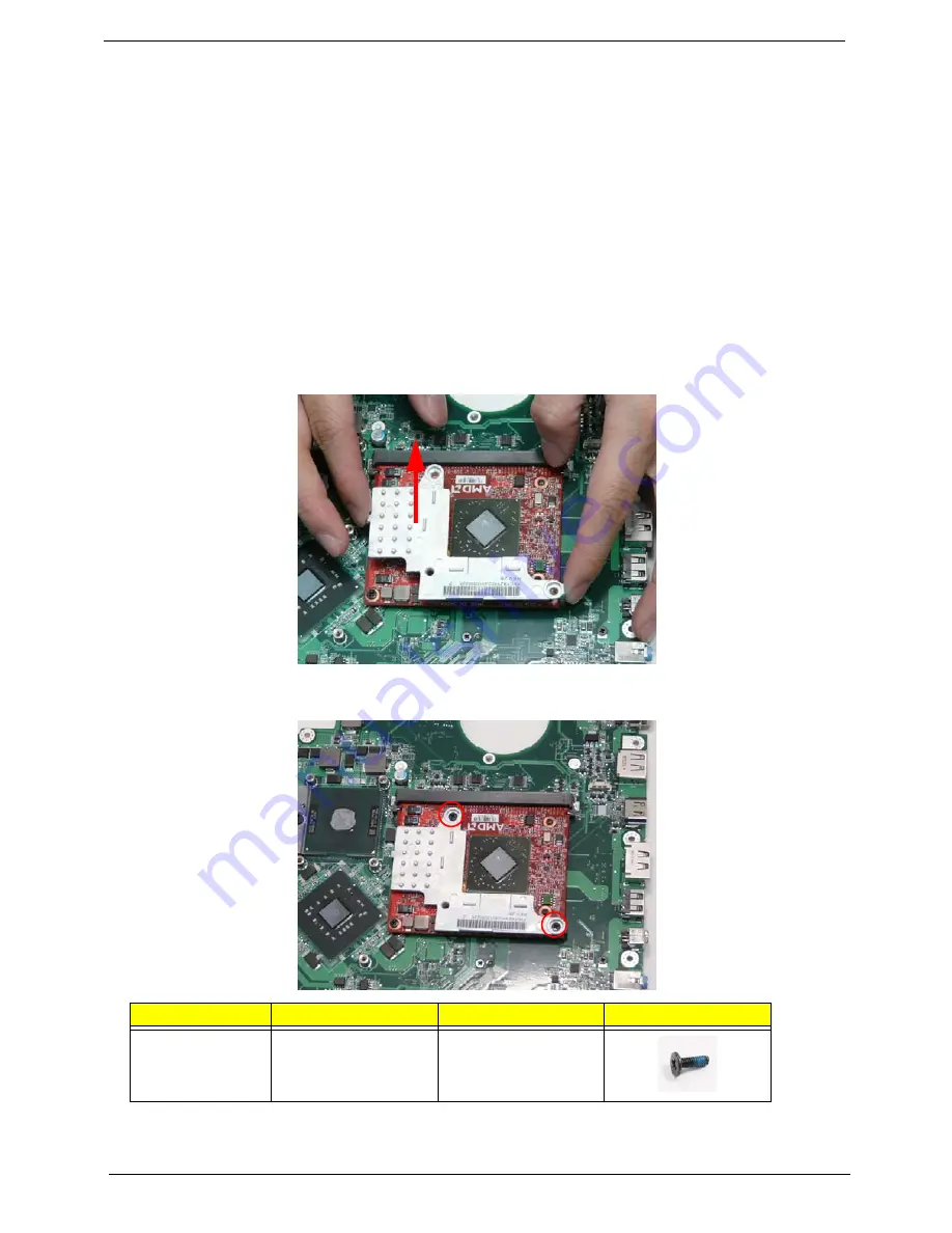
3.
Place the heatsink onto from the Graphics Card as shown.
4.
Replace the two screws (in numerical order from 1 to 2) to secure the Graphics Card Heatsink to the
Mainboard.
Step
Size
Quantity
Screw Type
Graphics Card
Heatsink
M2.5*6.5
2
1
2
Summary of Contents for Aspire 8935G
Page 6: ...VI ...
Page 44: ...34 Chapter 1 ...
Page 62: ...52 Chapter 2 ...
Page 78: ...68 Chapter 3 4 Remove the TV Tuner as shown ...
Page 80: ...70 Chapter 3 4 Detach the WLAN Module from the WLAN socket ...
Page 97: ...Chapter 3 87 5 Lift the board clear of the Upper Cover ...
Page 100: ...90 Chapter 3 5 Lift the Media Board clear of the Upper Cover ...
Page 106: ...96 Chapter 3 8 Lift the board clear of the Upper Cover ...
Page 109: ...Chapter 3 99 5 Remove the Bluetooth Board from the Lower Cover ...
Page 118: ...108 Chapter 3 4 Using both hands lift the Subwoofer clear of the Lower Cover ...
Page 155: ...Chapter 3 145 3 Press down around the perimeter of the bezel to secure it in place ...
Page 173: ...Chapter 3 163 4 Connect the Bluetooth cable to the Mainboard ...
Page 184: ...174 Chapter 3 4 Connect the Volume Control FFC to the Media Board and close the locking latch ...
Page 202: ...192 Chapter 3 2 Tighten the seven captive screws in the Lower Door ...
Page 204: ...194 Chapter 3 ...
Page 239: ...Chapter 6 229 ...
Page 316: ...306 Appendix C ...
Page 320: ...310 ...