


Chapter 3
179
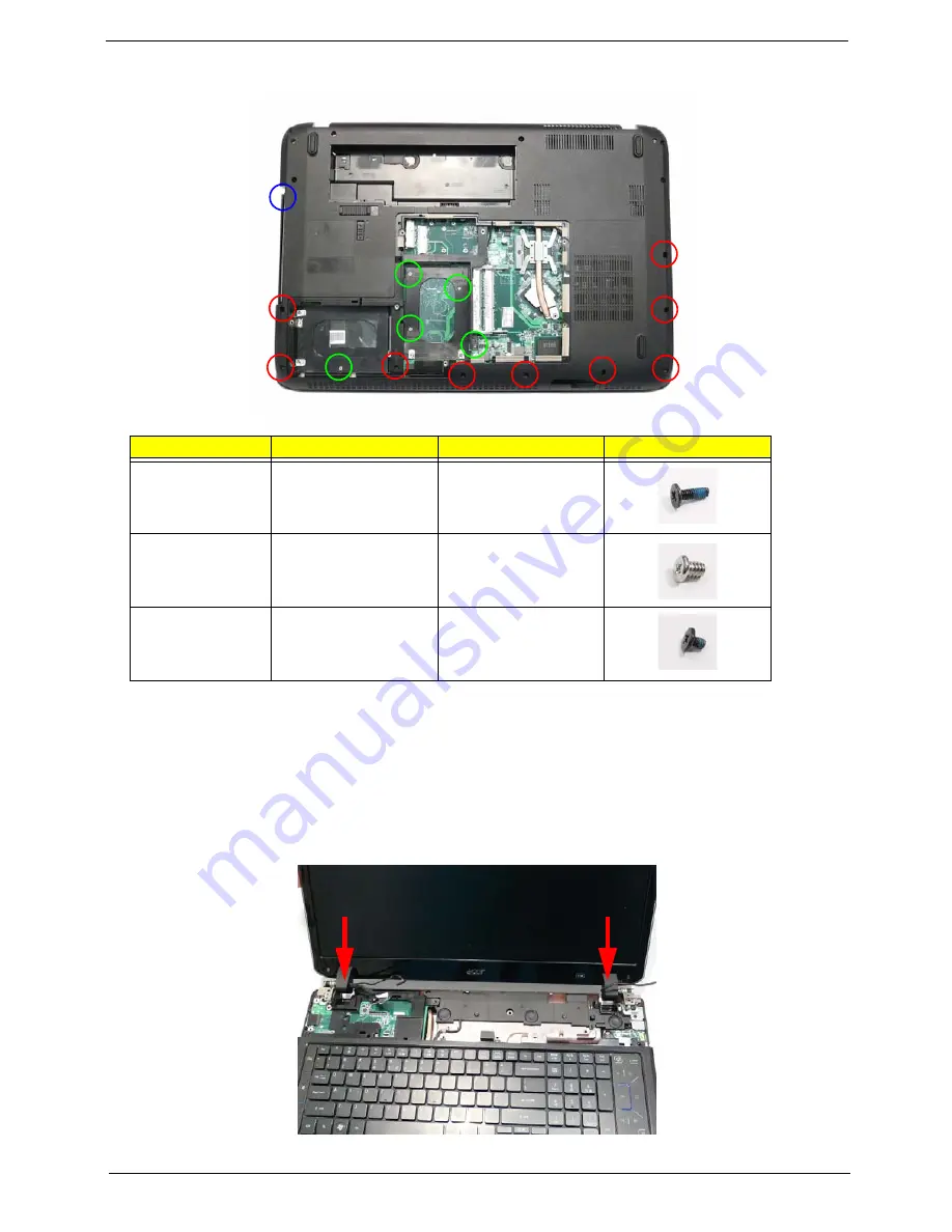
2.
Turn the computer over. Replace the fifteen screws on the bottom panel.
Replacing the LCD Module
1.
Using both hands, set the LCD Module into the Lower Cover, taking care to set the mounting pins into the
bottom cover.
NOTE:
Ensure that the antenna, microphone, and LVDS cables pass through the openings on the hinge wells
before securing the LCD module in place.
Step
Size
Quantity
Screw Type
Upper Cover
(red callout)
M2.5*6.5
9
Upper Cover
(green callout)
M2.5*4
5
Upper Cover
(blue callout)
M2*3
1
Summary of Contents for Aspire 8935G
Page 6: ...VI ...
Page 44: ...34 Chapter 1 ...
Page 62: ...52 Chapter 2 ...
Page 78: ...68 Chapter 3 4 Remove the TV Tuner as shown ...
Page 80: ...70 Chapter 3 4 Detach the WLAN Module from the WLAN socket ...
Page 97: ...Chapter 3 87 5 Lift the board clear of the Upper Cover ...
Page 100: ...90 Chapter 3 5 Lift the Media Board clear of the Upper Cover ...
Page 106: ...96 Chapter 3 8 Lift the board clear of the Upper Cover ...
Page 109: ...Chapter 3 99 5 Remove the Bluetooth Board from the Lower Cover ...
Page 118: ...108 Chapter 3 4 Using both hands lift the Subwoofer clear of the Lower Cover ...
Page 155: ...Chapter 3 145 3 Press down around the perimeter of the bezel to secure it in place ...
Page 173: ...Chapter 3 163 4 Connect the Bluetooth cable to the Mainboard ...
Page 184: ...174 Chapter 3 4 Connect the Volume Control FFC to the Media Board and close the locking latch ...
Page 202: ...192 Chapter 3 2 Tighten the seven captive screws in the Lower Door ...
Page 204: ...194 Chapter 3 ...
Page 239: ...Chapter 6 229 ...
Page 316: ...306 Appendix C ...
Page 320: ...310 ...