


8
Chapter 1
Right View
3
External display
(VGA) port
Connects to a display device (e.g. external, LCD monitor,
LCD projector).
4
HDMI
HDMI port
Supports high definition digital video connections.
5
Ethernet RJ-45)
port
Connects to an Ethernet 10/100/1000-based network.
6
USB 2.0 port
Connects to USB 2.0 devices (e.g., USB mouse, USB
camera).
7
Microphone jack
Accepts inputs from external microphones.
Headphones/
speaker/line-out
jack with S/PDIF
support.
Connects to audio line-out devices (e.g., speakers,
headphones).
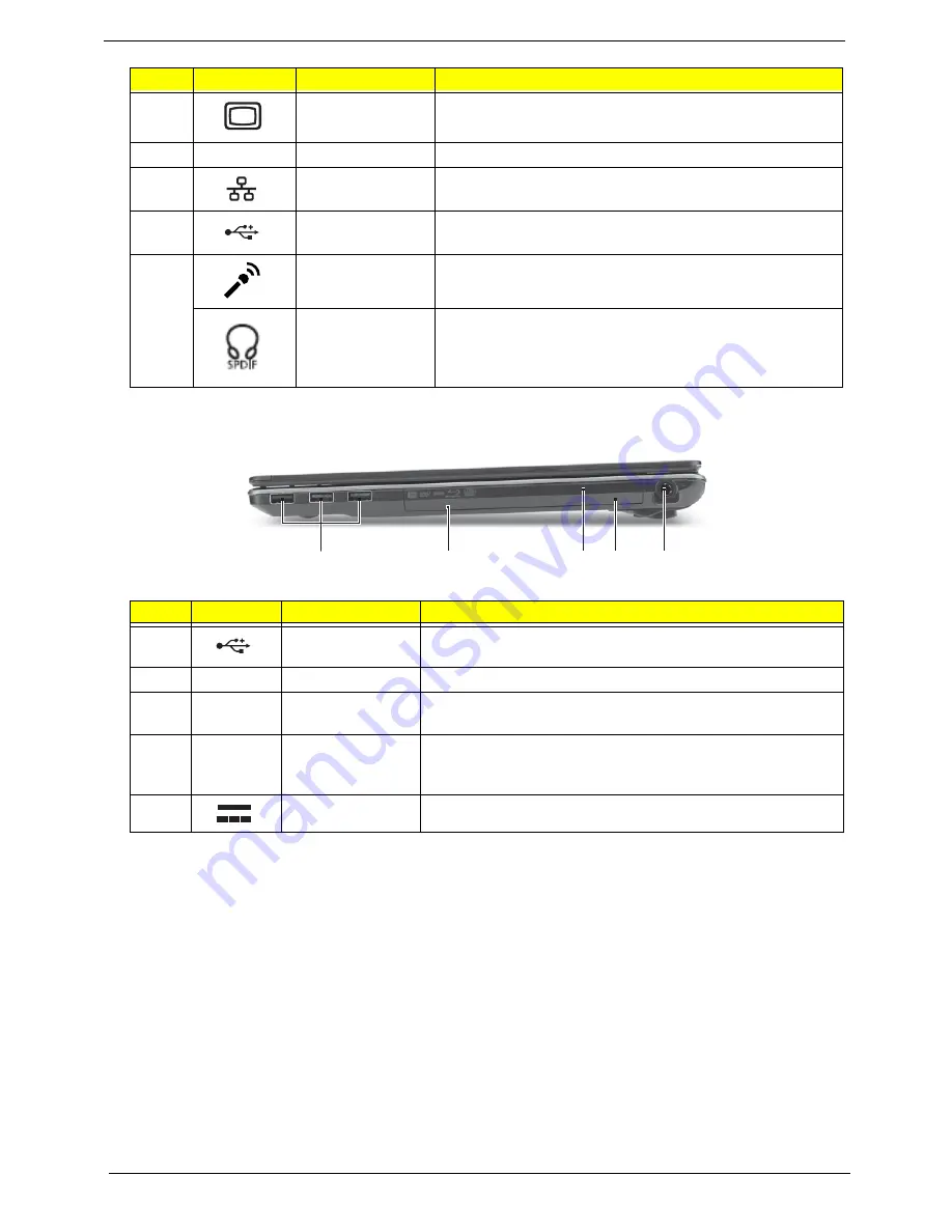
#
Icon
Item
Description
1
USB 2.0 port
Connects to USB 2.0 devices (e.g., USB mouse, USB
camera).
2
Optical drive
Internal optical drive; accepts CDs or DVDs.
3
Optical disk
access indicator
Lights up when the optical drive is active.
4
Emergency eject
hole
Ejects the optical drive tray when the computer is turned
off.Note: Insert a paper clip to the emergency eject hole to
eject the optical drive tray when the computer is off.
5
DC-in jack
Connects to an AC adapter.
#
Icon
Item
Description
2
1
3 4
5
Summary of Contents for ASPIRE 553G
Page 6: ...VI ...
Page 10: ...X Table of Contents ...
Page 42: ...32 Chapter 1 ...
Page 67: ...Chapter 3 57 4 Lift the base door out and away ...
Page 72: ...62 Chapter 3 5 Pull the WLAN module out and away ...
Page 86: ...76 Chapter 3 4 Unlock and disconnect the switch board FFC ...
Page 88: ...78 Chapter 3 4 Lift the power board away ...
Page 93: ...Chapter 3 83 14 Lift the LCD module out of the assembly ...
Page 111: ...Chapter 3 101 7 Disconnect the FPC cable ...
Page 114: ...104 Chapter 3 8 Remove the cable from the retention guides 9 Pry the antenna off the casing ...
Page 119: ...Chapter 3 109 7 Lay the cables along the retention guides ...
Page 134: ...124 Chapter 3 4 Connect and lock the USB card FFC to the mainboard ...
Page 136: ...126 Chapter 3 4 Connect the Bluetooth module cable to the main board ...
Page 146: ...136 Chapter 3 7 Connect and lock the button board FFC ...
Page 152: ...142 Chapter 3 4 Grasp the tab and slide the HDD firmly into the docking connector ...
Page 154: ...144 Chapter 3 Replacing the ODD Module 1 Replace the ODD bezel 2 Replace the ODD bracket ...
Page 158: ...148 Chapter 3 ...
Page 178: ...168 Chapter 5 ...
Page 228: ...218 Appendix A ...
Page 234: ...224 Appendix B ...
Page 236: ...226 ...
Page 239: ...229 Index ...


