Chapter 1
9
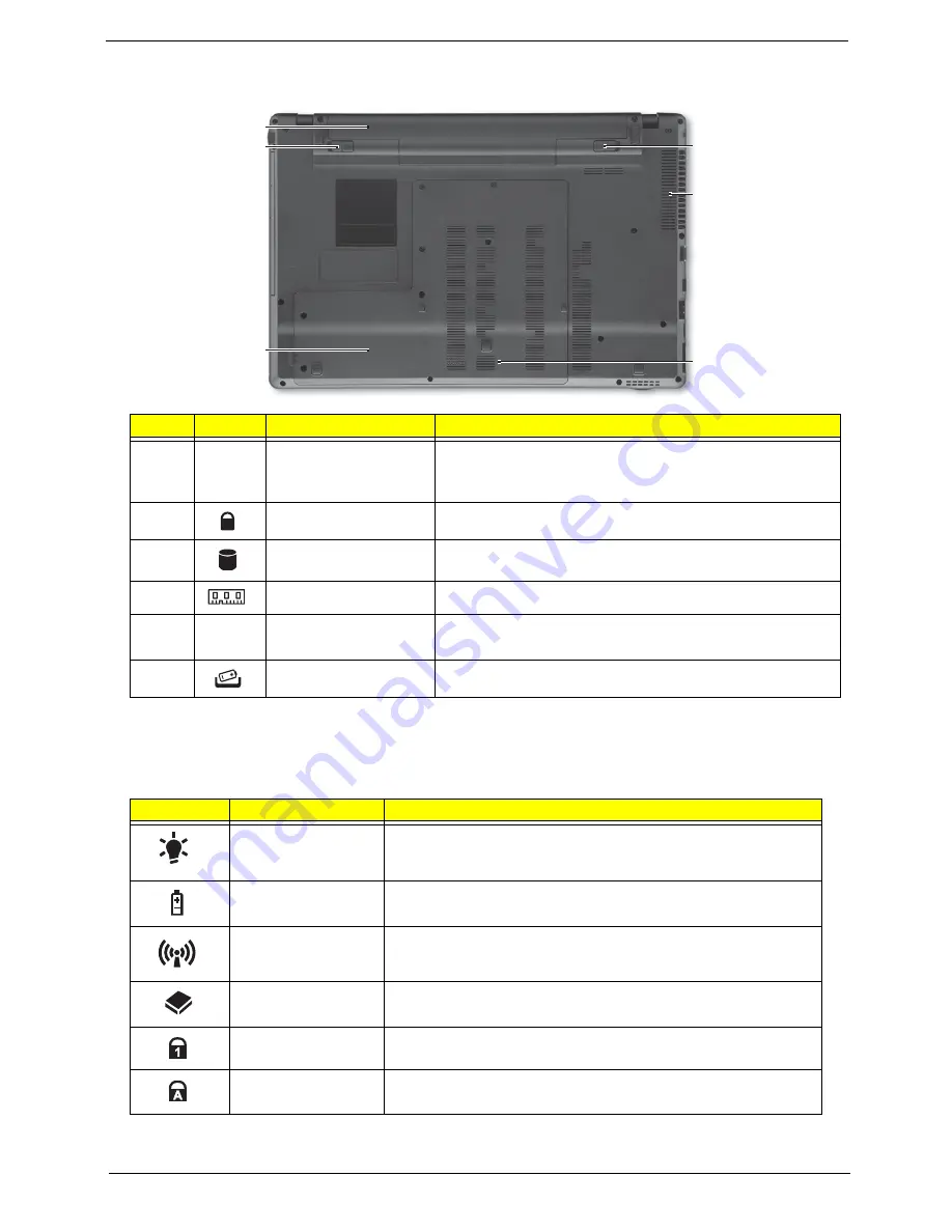
Base View
Indicators
The computer has several easy-to-read status indicators. The battery indicator is visible even when the
computer cover is closed.
NOTE:
1.
Charging:
The battery light shows amber when the battery is charging. 2.
Fully charged:
The light
shows green when in AC mode.
#
Icon
Item
Description
1
Battery bay
Houses the computer’s battery pack.
Note: The battery shown is for reference only. Your PC may
have a different battery depending on the model purchased.
2
Battery lock
Locks the battery in position
3
Hard disk bay
Houses the computer’s hard disk (secured with screws)
4
Memory compartment
Houses the computer’s main memory.
5
Ventilation slots and
cooling fan
Enable the computer to stay cool, even after prolonged use.
Note: Do not cover or obstruct the opening the fan.
6
Battery release latch
Releases the battery for removal.
Icon
Function
Description
Power
Indicates the computer is on or off.
Battery
Indicates the computer's battery status.
Wireless LAN
Indicates the status of Wireless LAN communication.
HDD
Indicates when the hard disk drive is active.
Num Lock
Lights up when Num Lock is activated.
Caps Lock
Lights up when Caps Lock is activated.
1
2
3
4
5
6
Summary of Contents for ASPIRE 553G
Page 6: ...VI ...
Page 10: ...X Table of Contents ...
Page 42: ...32 Chapter 1 ...
Page 67: ...Chapter 3 57 4 Lift the base door out and away ...
Page 72: ...62 Chapter 3 5 Pull the WLAN module out and away ...
Page 86: ...76 Chapter 3 4 Unlock and disconnect the switch board FFC ...
Page 88: ...78 Chapter 3 4 Lift the power board away ...
Page 93: ...Chapter 3 83 14 Lift the LCD module out of the assembly ...
Page 111: ...Chapter 3 101 7 Disconnect the FPC cable ...
Page 114: ...104 Chapter 3 8 Remove the cable from the retention guides 9 Pry the antenna off the casing ...
Page 119: ...Chapter 3 109 7 Lay the cables along the retention guides ...
Page 134: ...124 Chapter 3 4 Connect and lock the USB card FFC to the mainboard ...
Page 136: ...126 Chapter 3 4 Connect the Bluetooth module cable to the main board ...
Page 146: ...136 Chapter 3 7 Connect and lock the button board FFC ...
Page 152: ...142 Chapter 3 4 Grasp the tab and slide the HDD firmly into the docking connector ...
Page 154: ...144 Chapter 3 Replacing the ODD Module 1 Replace the ODD bezel 2 Replace the ODD bracket ...
Page 158: ...148 Chapter 3 ...
Page 178: ...168 Chapter 5 ...
Page 228: ...218 Appendix A ...
Page 234: ...224 Appendix B ...
Page 236: ...226 ...
Page 239: ...229 Index ...


