


Chapter 4
157
9.
Restore system and file settings from a known good date using
System
Restore
.
If the issue is not fixed, repeat the preceding steps and select an earlier time and date.
10.
Reinstall the Operating System.
11.
If the Issue is still not resolved, see “Online Support Information” on page 225.
Internal Microphone Failure
If the internal
Microphone
fails, perform the following actions one at a time to correct the problem. Do not
replace non-defective FRUs:
Microphone Problems
If internal or external
Microphones
do no operate correctly, perform the following actions one at a time to
correct the problem.
1.
Check that the microphone is enabled. Navigate to
Start
´
Control
Panel
´
Hardware
and
Sound
´
Sound
and select the
Recording
tab.
2.
Right-click on the
Recording
tab and select
Show
Disabled
Devices
(clear by default).
3.
The microphone appears on the
Recording
tab.
4.
Right-click on the microphone and select
Enable
.
5.
Select the microphone then click
Properties
. Select the
Levels
tab.
6.
Increase the volume to the maximum setting and click
OK
.
7.
Test the microphone hardware:
a.
Select the microphone and click
Configure
.
b.
Select
Set up microphone
.
c.
Select the microphone type from the list and click
Next
.
d.
Follow the onscreen prompts to complete the test.
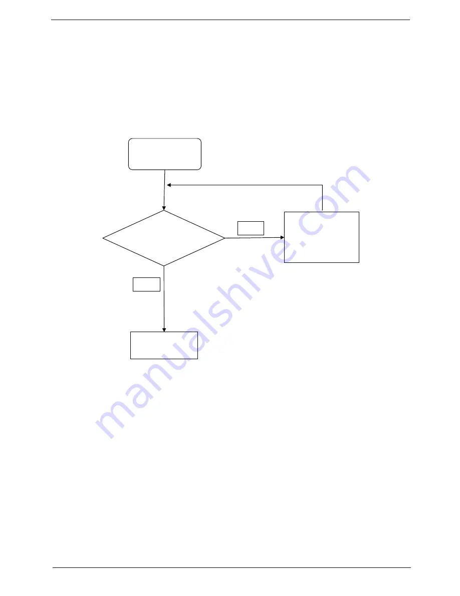
Start
Check M/B Mic.
cable
Re-assemble the
MIC cable to M/B
NG
Swap M/B
OK
Summary of Contents for ASPIRE 553G
Page 6: ...VI ...
Page 10: ...X Table of Contents ...
Page 42: ...32 Chapter 1 ...
Page 67: ...Chapter 3 57 4 Lift the base door out and away ...
Page 72: ...62 Chapter 3 5 Pull the WLAN module out and away ...
Page 86: ...76 Chapter 3 4 Unlock and disconnect the switch board FFC ...
Page 88: ...78 Chapter 3 4 Lift the power board away ...
Page 93: ...Chapter 3 83 14 Lift the LCD module out of the assembly ...
Page 111: ...Chapter 3 101 7 Disconnect the FPC cable ...
Page 114: ...104 Chapter 3 8 Remove the cable from the retention guides 9 Pry the antenna off the casing ...
Page 119: ...Chapter 3 109 7 Lay the cables along the retention guides ...
Page 134: ...124 Chapter 3 4 Connect and lock the USB card FFC to the mainboard ...
Page 136: ...126 Chapter 3 4 Connect the Bluetooth module cable to the main board ...
Page 146: ...136 Chapter 3 7 Connect and lock the button board FFC ...
Page 152: ...142 Chapter 3 4 Grasp the tab and slide the HDD firmly into the docking connector ...
Page 154: ...144 Chapter 3 Replacing the ODD Module 1 Replace the ODD bezel 2 Replace the ODD bracket ...
Page 158: ...148 Chapter 3 ...
Page 178: ...168 Chapter 5 ...
Page 228: ...218 Appendix A ...
Page 234: ...224 Appendix B ...
Page 236: ...226 ...
Page 239: ...229 Index ...


