


Chapter 2
39
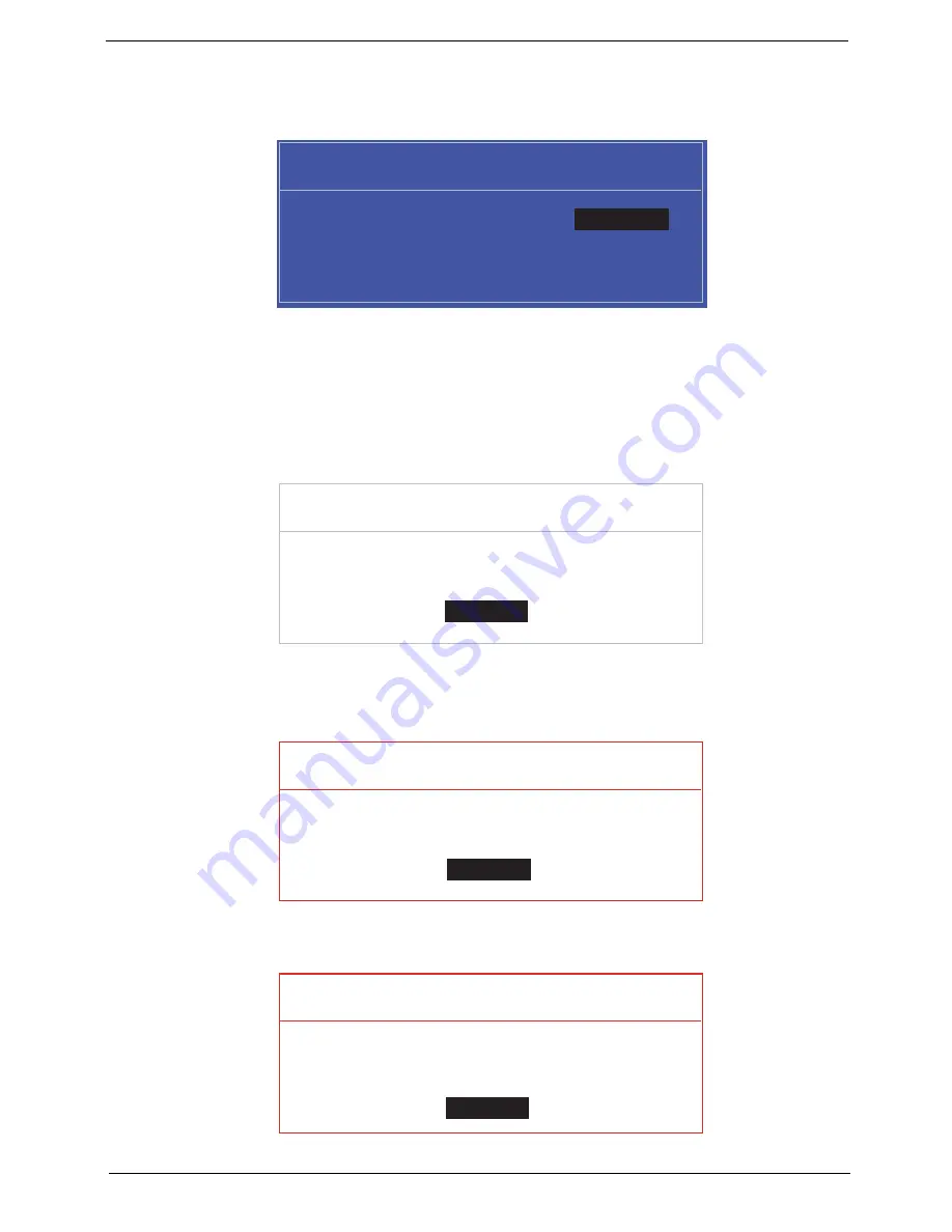
Changing a Password
1.
Use the
↑
and
↓
keys to highlight the Set Supervisor Password parameter and press the
Enter
key. The
Set Password box appears.
2.
Type the current password in the Enter Current Password field and press
Enter
.
3.
Type a password in the Enter New Password field. Retype the password in the Confirm New Password
field.
4.
Press
Enter
. After setting the password, the computer sets the User Password parameter to “Set”.
5.
If desired, you can enable the Password on boot parameter.
6.
When you are done, press
F10
to save the changes and exit the BIOS Setup Utility.
If the verification is OK, the screen will display as following.
The password setting is complete after the user presses
Enter
.
If the current password entered does not match the actual current password, the screen will show you the
Setup Warning.
If the new password and confirm new password strings do not match, the screen displays the following
message.
S e t S u p e r v i s o r P a s s w o r d
E n t e r C u r r e n t P a s s w o r d [ ]
[ ]
E n t e r N e w P a s s w o r d [ ]
C o n f i r m N e w P a s s w o r d [ ]
[ ]
S e t u p N o t i c e
C h a n g e s h a v e b e e n s a v e d .
[ C o n t i n u e ]
[
C o n t i n u e
]
S e t u p W a r n i n g
I n v a l i d P a s s w o r d .
[ C o n t i n u e ]
[
C o n t i n u e
]
S e t u p W a r n i n g
P a s s w o r d s d o n o t m a t c h .
R e - e n t e r p a s s w o r d .
[ C o n t i n u e ]
[
C o n t i n u e
]
Summary of Contents for ASPIRE 553G
Page 6: ...VI ...
Page 10: ...X Table of Contents ...
Page 42: ...32 Chapter 1 ...
Page 67: ...Chapter 3 57 4 Lift the base door out and away ...
Page 72: ...62 Chapter 3 5 Pull the WLAN module out and away ...
Page 86: ...76 Chapter 3 4 Unlock and disconnect the switch board FFC ...
Page 88: ...78 Chapter 3 4 Lift the power board away ...
Page 93: ...Chapter 3 83 14 Lift the LCD module out of the assembly ...
Page 111: ...Chapter 3 101 7 Disconnect the FPC cable ...
Page 114: ...104 Chapter 3 8 Remove the cable from the retention guides 9 Pry the antenna off the casing ...
Page 119: ...Chapter 3 109 7 Lay the cables along the retention guides ...
Page 134: ...124 Chapter 3 4 Connect and lock the USB card FFC to the mainboard ...
Page 136: ...126 Chapter 3 4 Connect the Bluetooth module cable to the main board ...
Page 146: ...136 Chapter 3 7 Connect and lock the button board FFC ...
Page 152: ...142 Chapter 3 4 Grasp the tab and slide the HDD firmly into the docking connector ...
Page 154: ...144 Chapter 3 Replacing the ODD Module 1 Replace the ODD bezel 2 Replace the ODD bracket ...
Page 158: ...148 Chapter 3 ...
Page 178: ...168 Chapter 5 ...
Page 228: ...218 Appendix A ...
Page 234: ...224 Appendix B ...
Page 236: ...226 ...
Page 239: ...229 Index ...


