28
Chapter 1
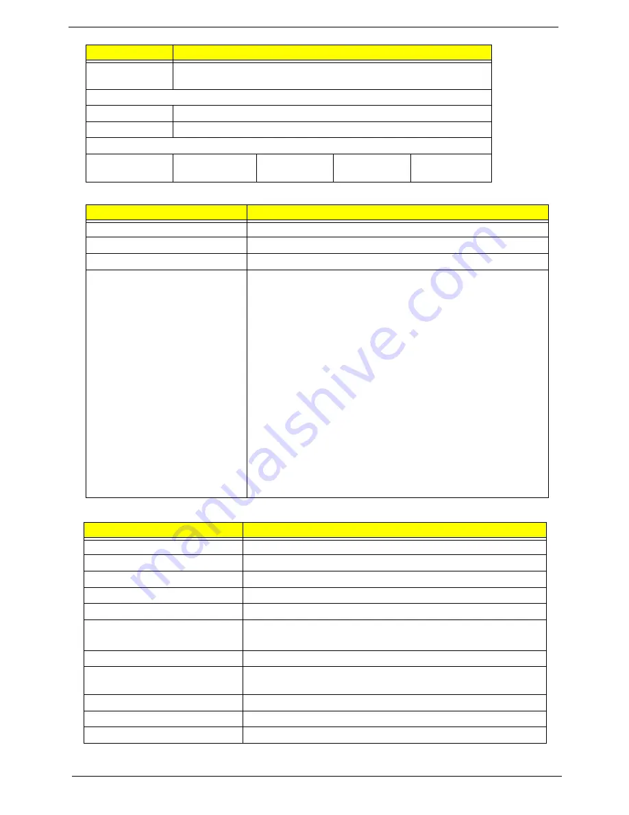
BIOS
LCD 15.6”
Spindle speed
(RPM)
5400
Performance Specifications
Buffer size
8 MB
Interface
SATA
DC Power Requirements
Voltage
tolerance
5V ±5%
5V ±5%
5V ±5%
5V ±5%
Item
Specification
BIOS vendor
Phoenix
BIOS version
Release 4.0
BIOS ROM type
Flash
Features
•
Flash ROM 4MB
•
Support ISIPP
•
Support Acer UI
•
Support multi-boot
•
Suspend to RAM (S3)/Disk (S4)
•
Various hot-keys for system control
•
Support SMBIOS 2.3, PCI2.2.
•
Refer to Acer BIOS specification.
•
DMI utility for BIOS serial number configurable/asset tag
•
Support PXE
•
Support Y2K solution
•
Support WinFlash
•
Wake on LAN from S3
•
Wake on LAN form S4 in AC mode
•
System information
Item
Specification
Vendor/model name
AUO/Samsung/LG
Screen Diagonal (mm)
15.6 inches
Display resolution (pixels)
1366 x 768
Pixel Pitch
0.252x 0.252
Display Mode
Normally White
Typical White Luminance (cd/m
2
)
(also called Brightness)
200
Contrast Ratio
500 typical
Response Time (Optical Rise
Time/Fall Time) msec
8/16
Luminance Uniformity
1.25 max
Electrical Interface
LVDS
Support Color
262K
Item
Specification
Summary of Contents for ASPIRE 553G
Page 6: ...VI ...
Page 10: ...X Table of Contents ...
Page 42: ...32 Chapter 1 ...
Page 67: ...Chapter 3 57 4 Lift the base door out and away ...
Page 72: ...62 Chapter 3 5 Pull the WLAN module out and away ...
Page 86: ...76 Chapter 3 4 Unlock and disconnect the switch board FFC ...
Page 88: ...78 Chapter 3 4 Lift the power board away ...
Page 93: ...Chapter 3 83 14 Lift the LCD module out of the assembly ...
Page 111: ...Chapter 3 101 7 Disconnect the FPC cable ...
Page 114: ...104 Chapter 3 8 Remove the cable from the retention guides 9 Pry the antenna off the casing ...
Page 119: ...Chapter 3 109 7 Lay the cables along the retention guides ...
Page 134: ...124 Chapter 3 4 Connect and lock the USB card FFC to the mainboard ...
Page 136: ...126 Chapter 3 4 Connect the Bluetooth module cable to the main board ...
Page 146: ...136 Chapter 3 7 Connect and lock the button board FFC ...
Page 152: ...142 Chapter 3 4 Grasp the tab and slide the HDD firmly into the docking connector ...
Page 154: ...144 Chapter 3 Replacing the ODD Module 1 Replace the ODD bezel 2 Replace the ODD bracket ...
Page 158: ...148 Chapter 3 ...
Page 178: ...168 Chapter 5 ...
Page 228: ...218 Appendix A ...
Page 234: ...224 Appendix B ...
Page 236: ...226 ...
Page 239: ...229 Index ...