170
Chapter 5
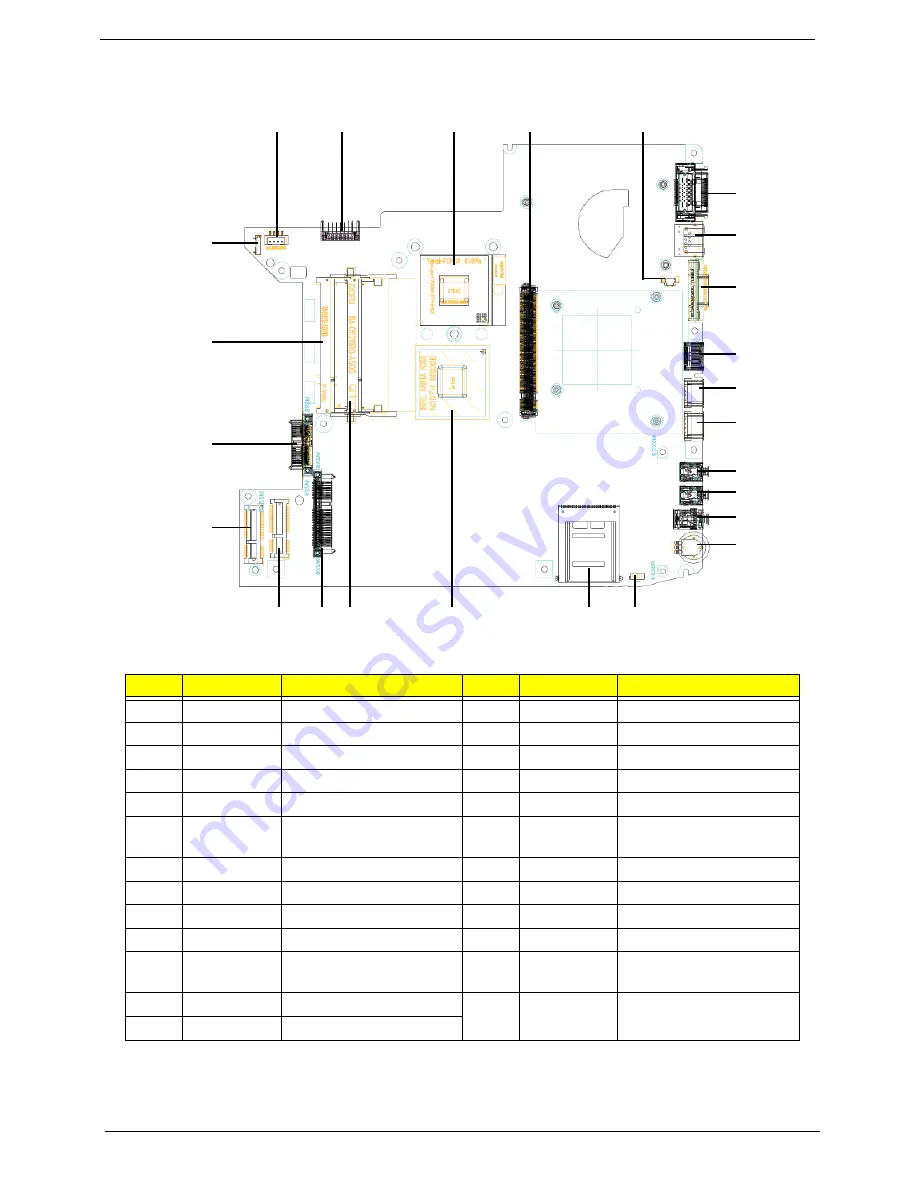
Bottom View
No.
Item
Description
No.
Item
Description
1
PJP1
AC-IN Connector
14
JHP1
Head-Phone Connector
2
PJP2
Battery Connector
15
U39
Volume control wheel
3
JCPU1
CPU Socket
16
IR1
IR receiver
4
JMXM1
MXM Board Connector
17
JREAD1
Card Reader Socket
5
JP12
Fan Connector
18
U31
North Bridge
6
JDOCK1
Dock Connector
19
JDIMM2
Memory DIMM2
Connector
7
JRJ45
RJ45 Connector
20
JSATA2
HDD Connector
8
JCRT1
CRT Connector
21
JMINI2
Wireless Card Connector
9
JHDMI1
HDMI Connector
22
JMINI1
Robson II Connector
10
JUSB1
USB Connector
23
JSATA1
ODD Connector
11
JUSB2
USB Connector
24
JDIMM1
Memory DIMM1
Connector
12
JLINE1
Line-In Jack
25
JP11
USB/B Connector
13
JMIC1
MIC-In Jack
1
2
3
4
5
6
7
8
9
10
11
12
13
14
15
16
17
18
19
20
21
22
23
24
25
Summary of Contents for Aspire 4930 Series
Page 6: ...VI ...
Page 10: ...X Table of Contents ...
Page 14: ...4 Chapter 1 System Block Diagram ...
Page 48: ...38 Chapter 1 ...
Page 63: ...Chapter 2 53 ...
Page 65: ...Chapter 2 55 ...
Page 66: ...56 Chapter 2 ...
Page 74: ...64 Chapter 3 6 Remove the HDD cover as shown 7 Remove the WLAN cover as shown ...
Page 79: ...Chapter 3 69 5 Remove the HDD from the carrier ...
Page 88: ...78 Chapter 3 Removing the Antenna 1 Remove the Antenna Cables from the securing pins as shown ...
Page 91: ...Chapter 3 81 6 Place the antenna cable as shown to avoid damaging them ...
Page 102: ...92 Chapter 3 13 Remove the Finger Print Reader board from the Upper Cover ...
Page 104: ...94 Chapter 3 13 Remove the Launch Board from the Upper Cover ...
Page 119: ...Chapter 3 109 18 Disconnect the DC IN Cable from the Mainboard ...
Page 121: ...Chapter 3 111 14 Lift the Thermal Module clear of the Mainboard ...
Page 123: ...Chapter 3 113 15 Lift the CPU clear of the Mainboard ...
Page 127: ...Chapter 3 117 14 Remove the HDMI Module as shown ...
Page 130: ...120 Chapter 3 10 Lift up the bezel rightside first and remove it from the LCD Module ...
Page 134: ...124 Chapter 3 11 Lift the Camera Module clear of the LCD Module ...
Page 138: ...128 Chapter 3 12 Remove the LCD brackets by pulling away from the LCD Panel as shown ...
Page 160: ...150 Chapter 3 ...
Page 191: ...Chapter 6 181 ...
Page 214: ...Appendix A 204 ...
Page 218: ...208 Appendix B ...
Page 220: ...210 Appendix C ...


