


6
Chapter 1
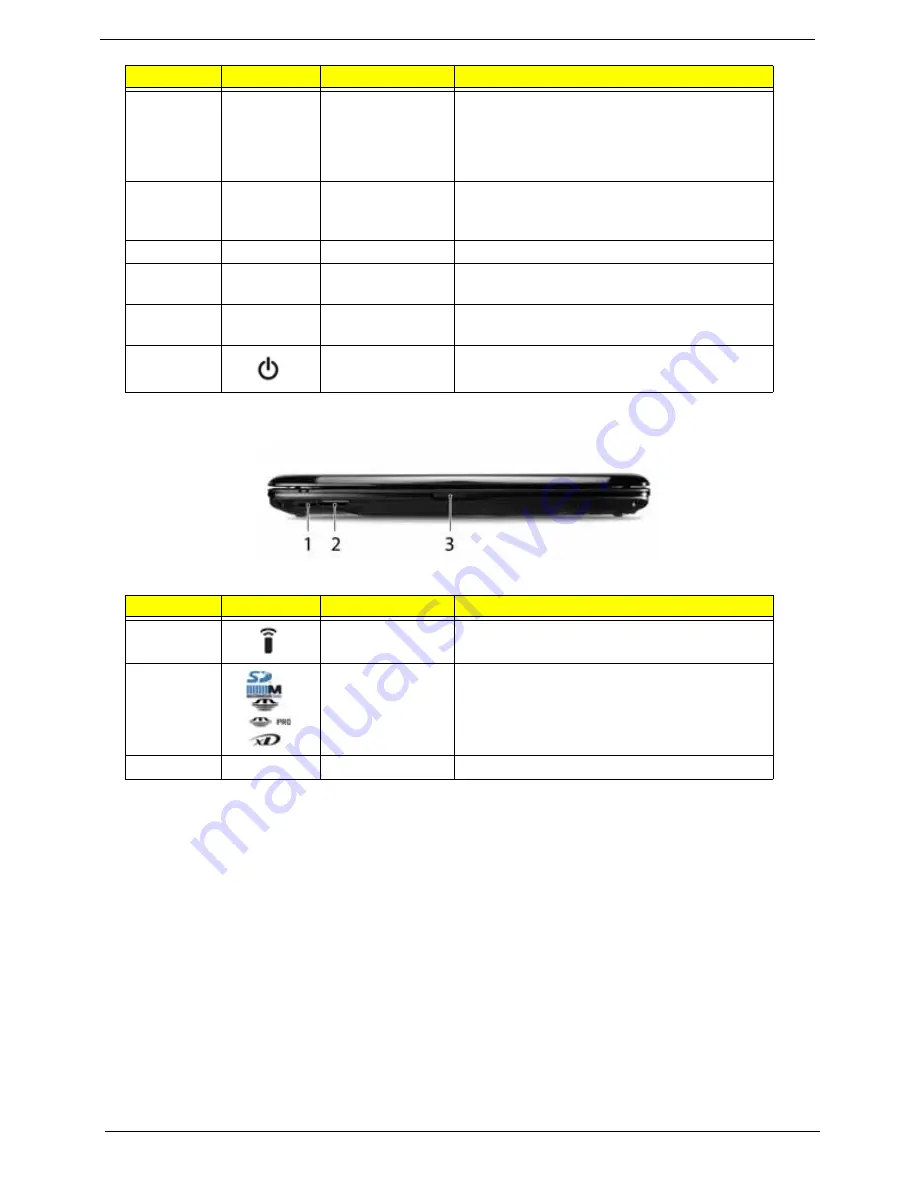
Closed Front View
9
Click buttons
(left, center* and
right)
The left and right buttons function like the left
and right mouse buttons. *The center button
serves as Acer Bio-Protection fingerprint
reader supporting Acer FingerNav 4-way
control function.
10
Status indicators
Light-Emitting Diodes (LEDs) that light up to
show the status of the computer's functions
and components.
11
Keyboard
For entering data into your computer.
12
Speakers
Left and right speakers deliver stereo audio
output.
13
Acer MediaTouch
keys
For use with Acer Arcade and other media
playing programs.
14
Power button
Turns the computer on and off.
No.
Icon
Item
Description
1
CIR receiver
Receives signals from a remote control.
2
5-in-1 card
reader
Accepts Secure Digital (SD), MultiMediaCard
(MMC), Memory Stick (MS), Memory Stick
PRO (MS PRO), xD-Picture Card (xD).
3
Latch
Locks and releases the lid
No.
Icon
Item
Description
Summary of Contents for Aspire 4930 Series
Page 6: ...VI ...
Page 10: ...X Table of Contents ...
Page 14: ...4 Chapter 1 System Block Diagram ...
Page 48: ...38 Chapter 1 ...
Page 63: ...Chapter 2 53 ...
Page 65: ...Chapter 2 55 ...
Page 66: ...56 Chapter 2 ...
Page 74: ...64 Chapter 3 6 Remove the HDD cover as shown 7 Remove the WLAN cover as shown ...
Page 79: ...Chapter 3 69 5 Remove the HDD from the carrier ...
Page 88: ...78 Chapter 3 Removing the Antenna 1 Remove the Antenna Cables from the securing pins as shown ...
Page 91: ...Chapter 3 81 6 Place the antenna cable as shown to avoid damaging them ...
Page 102: ...92 Chapter 3 13 Remove the Finger Print Reader board from the Upper Cover ...
Page 104: ...94 Chapter 3 13 Remove the Launch Board from the Upper Cover ...
Page 119: ...Chapter 3 109 18 Disconnect the DC IN Cable from the Mainboard ...
Page 121: ...Chapter 3 111 14 Lift the Thermal Module clear of the Mainboard ...
Page 123: ...Chapter 3 113 15 Lift the CPU clear of the Mainboard ...
Page 127: ...Chapter 3 117 14 Remove the HDMI Module as shown ...
Page 130: ...120 Chapter 3 10 Lift up the bezel rightside first and remove it from the LCD Module ...
Page 134: ...124 Chapter 3 11 Lift the Camera Module clear of the LCD Module ...
Page 138: ...128 Chapter 3 12 Remove the LCD brackets by pulling away from the LCD Panel as shown ...
Page 160: ...150 Chapter 3 ...
Page 191: ...Chapter 6 181 ...
Page 214: ...Appendix A 204 ...
Page 218: ...208 Appendix B ...
Page 220: ...210 Appendix C ...


