


5-4
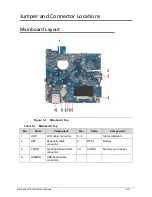
Jumper and Connector Locations
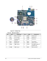
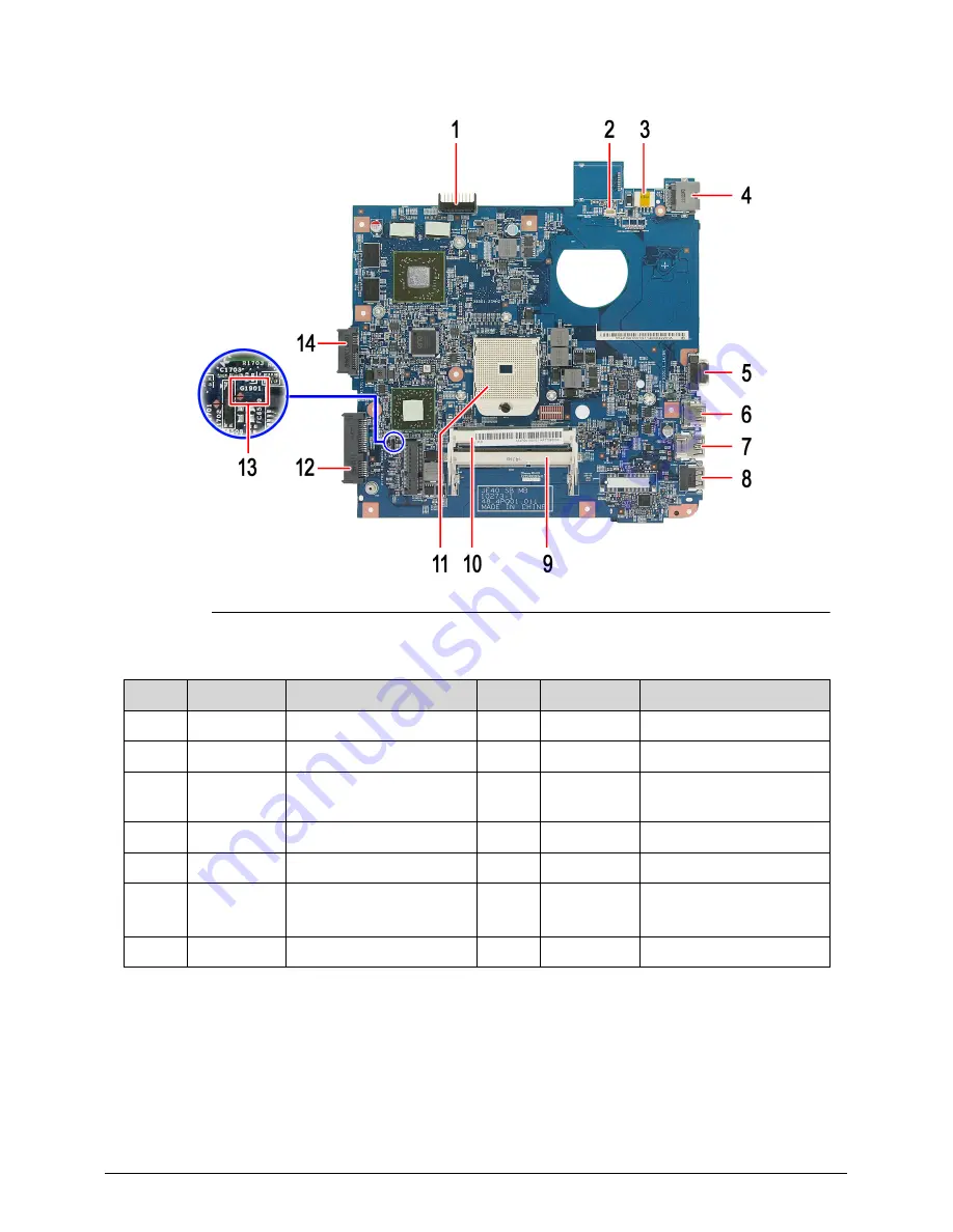
Figure 5-2. Bottom View
Table 5-2. Mainboard Bottom
No.
Code
Component
No.
Code
Component
1
BAT1
Battery connector
8
USB2
USB 2.0 port
2
FAN1
Fan connector
9
ADM2
DDR3 slot 2
3
DCIN1
DC input cable
connector
10
ADM1
DDR3 slot 1
4
RJ45
Ethernet jack
11
APU1
CPU socket
5
CRT1
Monitor port
12
HDD1
HDD connector
6
HDMI1
HDMI out port
13
G1901
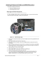
Clear BIOS password
hardware gap
7
AUSB1
USB 3.0 port
14
ODD1
ODD connector
Summary of Contents for Aspire 4560
Page 1: ... Aspire 4560 4560G SERVICEGUIDE ...
Page 10: ...x ...
Page 11: ...CHAPTER 1 Hardware Specifications ...
Page 14: ...1 4 ...
Page 51: ...CHAPTER 2 System Utilities ...
Page 67: ...CHAPTER 3 Machine Maintenance ...
Page 70: ...3 4 ...
Page 100: ...3 34 Machine Maintenance 4 Remove the USB board from the lower case Figure 3 44 USB Board ...
Page 109: ...Machine Maintenance 3 43 6 Remove the LCD module from the lower cover Figure 3 60 LCD Module ...
Page 162: ...3 96 Machine Maintenance ...
Page 163: ...CHAPTER 4 Troubleshooting ...
Page 193: ...CHAPTER 5 Jumper and Connector Locations ...
Page 200: ...5 8 Jumper and Connector Locations ...
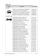
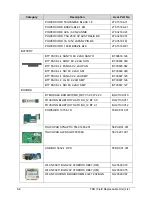
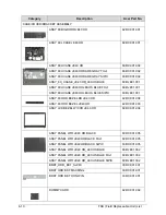
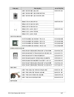
Page 201: ...CHAPTER 6 FRU List ...
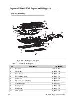
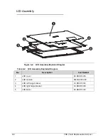
Page 202: ...6 2 Aspire 4560 4560G Exploded Diagram 6 4 Main Assembly 6 4 LCD Assembly 6 6 FRU List 6 7 ...
Page 217: ...CHAPTER 7 Model Definition and Configuration ...
Page 218: ...7 2 Aspire 4560 4560G 7 3 ...
Page 325: ...CHAPTER 8 Test Compatible Components ...
Page 326: ...8 2 Microsoft Windows 7 Environment Test 8 4 ...
Page 332: ...8 8 Test Compatible Components ...
Page 333: ...CHAPTER 9 Online Support Information ...
Page 334: ...9 2 Online Support Information 9 3 ...
Page 336: ...9 4 Online Support Information ...