
3-70
Machine Maintenance
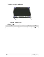
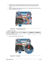
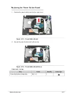
Replacing the Mainboard
0
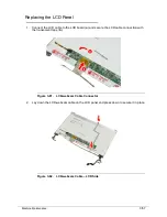
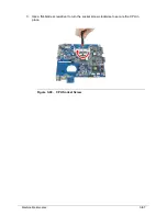
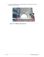
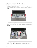
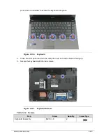
1. Connect the DC input cable to the mainboard.
Figure 3-103. DC input Cable
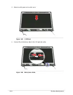
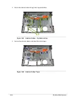
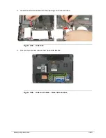
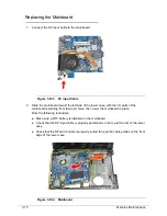
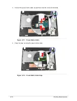
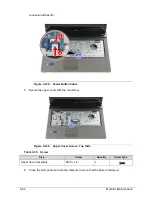
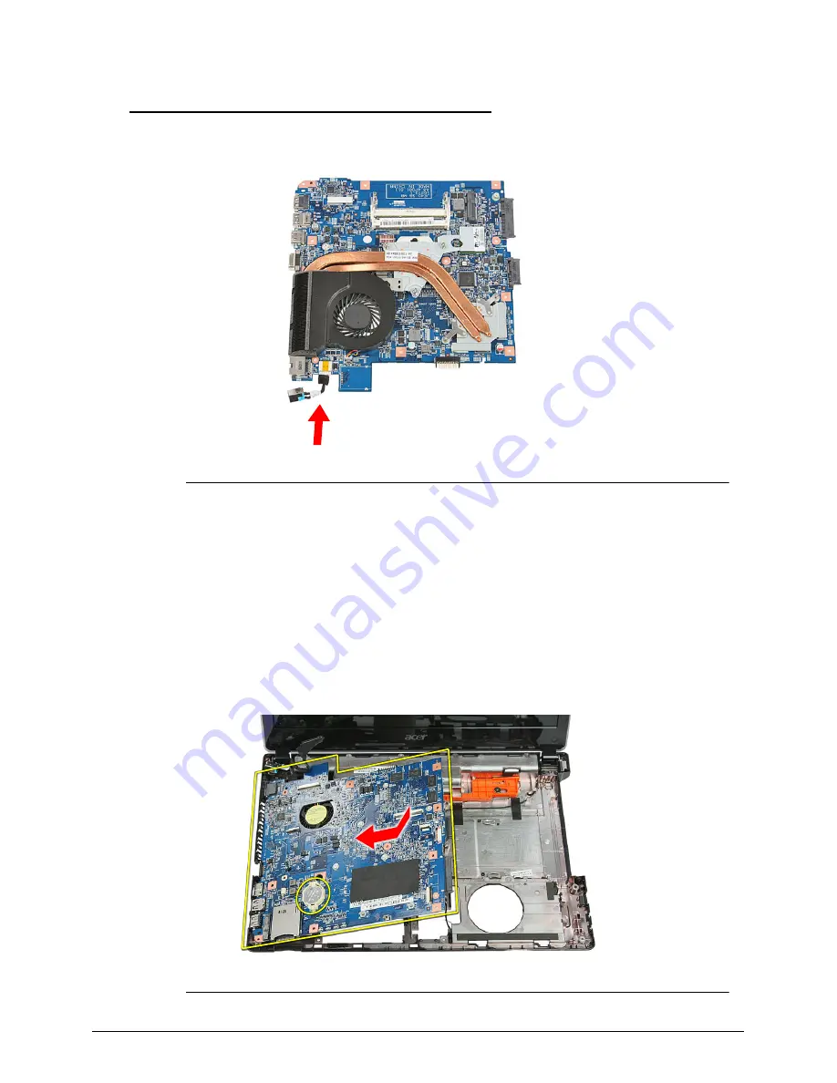
2. Slide the mainboard toward the left side of the lower case, with the I/O ports of the
mainboard extruding from their port holes, then lower the mainboard in place.
Note the following reminders:
Make sure a RTC battery is installed on the mainboard.
Check that the DC input cable is properly positioned on the top left corner of the lower
case.
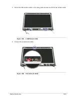
Check that the RF switch cable is properly routed through the cable guides on the front
edge of the lower case.
Figure 3-104. Mainboard
Summary of Contents for Aspire 4560
Page 1: ... Aspire 4560 4560G SERVICEGUIDE ...
Page 10: ...x ...
Page 11: ...CHAPTER 1 Hardware Specifications ...
Page 14: ...1 4 ...
Page 51: ...CHAPTER 2 System Utilities ...
Page 67: ...CHAPTER 3 Machine Maintenance ...
Page 70: ...3 4 ...
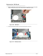
Page 100: ...3 34 Machine Maintenance 4 Remove the USB board from the lower case Figure 3 44 USB Board ...
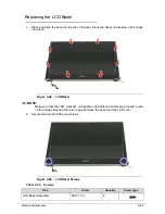
Page 109: ...Machine Maintenance 3 43 6 Remove the LCD module from the lower cover Figure 3 60 LCD Module ...
Page 162: ...3 96 Machine Maintenance ...
Page 163: ...CHAPTER 4 Troubleshooting ...
Page 193: ...CHAPTER 5 Jumper and Connector Locations ...
Page 200: ...5 8 Jumper and Connector Locations ...
Page 201: ...CHAPTER 6 FRU List ...
Page 202: ...6 2 Aspire 4560 4560G Exploded Diagram 6 4 Main Assembly 6 4 LCD Assembly 6 6 FRU List 6 7 ...
Page 217: ...CHAPTER 7 Model Definition and Configuration ...
Page 218: ...7 2 Aspire 4560 4560G 7 3 ...
Page 325: ...CHAPTER 8 Test Compatible Components ...
Page 326: ...8 2 Microsoft Windows 7 Environment Test 8 4 ...
Page 332: ...8 8 Test Compatible Components ...
Page 333: ...CHAPTER 9 Online Support Information ...
Page 334: ...9 2 Online Support Information 9 3 ...
Page 336: ...9 4 Online Support Information ...


