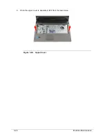

3-36
Machine Maintenance
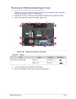
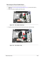
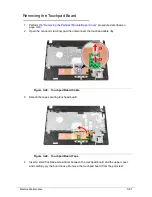
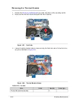
Removing the Mainboard
0
1. Perform the “
Removing the HDD Module
” and “
Removing the ODD Module
” procedures
described on pages
3-14
and
3-11
respectively.
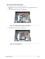
2. If a WLAN module is installed, remove it. Perform the “
Main Unit Disassembly Process
”
procedure described on pages
3-19
.
3. Perform the “
Removing the Palmrest Module/Upper Cover
” procedure described on
page
3-23
.
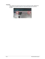
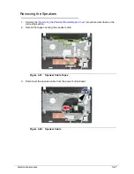
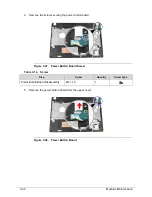
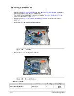
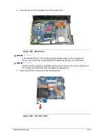
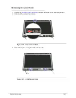
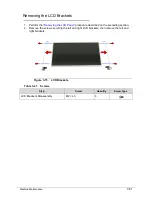
4. Disconnect the LCD cable from the mainboard.
Figure 3-47. LCD Cable
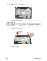
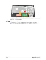
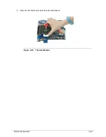
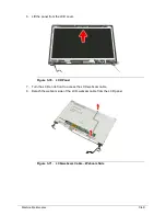
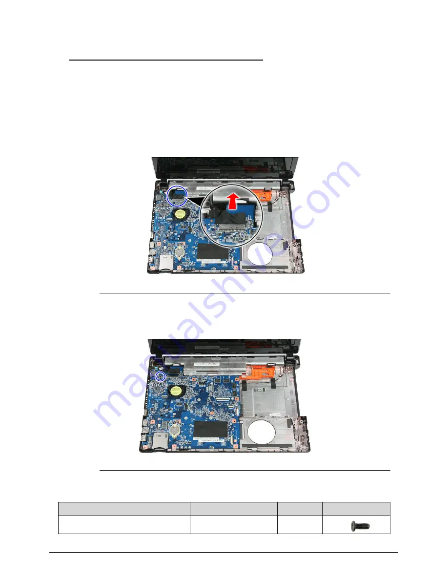
5. Remove the screw securing the mainboard.
Figure 3-48. Mainboard Screw
Table 3-15. Screw
Step
Screw
Quantity
Screw Type
Mainboard Disassembly
M2.5 x L6
1
Summary of Contents for Aspire 4560
Page 1: ... Aspire 4560 4560G SERVICEGUIDE ...
Page 10: ...x ...
Page 11: ...CHAPTER 1 Hardware Specifications ...
Page 14: ...1 4 ...
Page 51: ...CHAPTER 2 System Utilities ...
Page 67: ...CHAPTER 3 Machine Maintenance ...
Page 70: ...3 4 ...
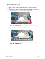
Page 100: ...3 34 Machine Maintenance 4 Remove the USB board from the lower case Figure 3 44 USB Board ...
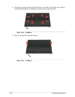
Page 109: ...Machine Maintenance 3 43 6 Remove the LCD module from the lower cover Figure 3 60 LCD Module ...
Page 162: ...3 96 Machine Maintenance ...
Page 163: ...CHAPTER 4 Troubleshooting ...
Page 193: ...CHAPTER 5 Jumper and Connector Locations ...
Page 200: ...5 8 Jumper and Connector Locations ...
Page 201: ...CHAPTER 6 FRU List ...
Page 202: ...6 2 Aspire 4560 4560G Exploded Diagram 6 4 Main Assembly 6 4 LCD Assembly 6 6 FRU List 6 7 ...
Page 217: ...CHAPTER 7 Model Definition and Configuration ...
Page 218: ...7 2 Aspire 4560 4560G 7 3 ...
Page 325: ...CHAPTER 8 Test Compatible Components ...
Page 326: ...8 2 Microsoft Windows 7 Environment Test 8 4 ...
Page 332: ...8 8 Test Compatible Components ...
Page 333: ...CHAPTER 9 Online Support Information ...
Page 334: ...9 2 Online Support Information 9 3 ...
Page 336: ...9 4 Online Support Information ...


