


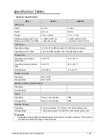
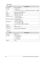
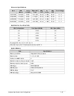
Hardware Specifications and Configurations
1-15
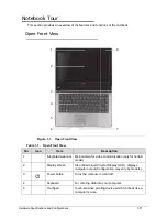
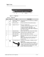
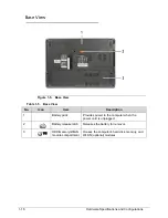
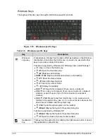
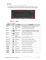
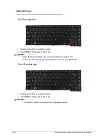
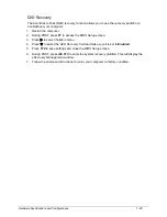
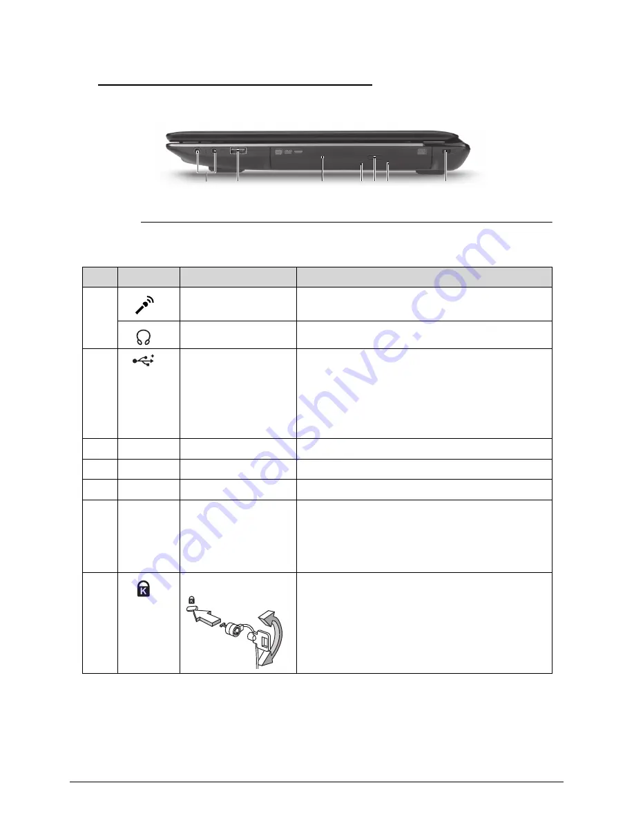
Right View
0
Figure 1-4. Right View
Table 1-4. Right View
No.
Icon
Item
Description
1
Headphones/speaker
/line-out jack
Connects to audio line-out devices (e.g., speakers,
headphone).
Microphone jack
Accepts inputs from an external microphone.
2
USB 2.0/3.0* port
Connects to USB devices.
* A USB 3.0 port can be distinguished by its blue
connector (for certain models only).
* Supports the USB 3.0 (SuperSpeed USB)
specification; Devices without USB 3.0 certification
may not be compatible.
3
Optical disc drive
Internal optical disc drive; accepts CDs or DVDs.
4
ODD access indicator Lights up when the optical drive is active.
5
ODD eject button
Ejects the optical disc from the drive.
6
ODD emergency
eject hole
Ejects the optical drive tray when the computer is
turned off.
Note:
Insert a paper clip to the emergency eject
hole to eject the optical drive tray when the
computer is off.
7
Kensington lock slot
Connects to a Kensington-compatible computer
security lock.
Note:
Wrap the computer security lock cable
around an immovable object such as a table or the
handle of a locked drawer. Insert the lock into the
notch and turn the key to secure the lock. Some
keyless models are also available.
2
1
3
4
7
5 6
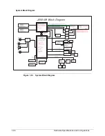
Summary of Contents for Aspire 4560
Page 1: ... Aspire 4560 4560G SERVICEGUIDE ...
Page 10: ...x ...
Page 11: ...CHAPTER 1 Hardware Specifications ...
Page 14: ...1 4 ...
Page 51: ...CHAPTER 2 System Utilities ...
Page 67: ...CHAPTER 3 Machine Maintenance ...
Page 70: ...3 4 ...
Page 100: ...3 34 Machine Maintenance 4 Remove the USB board from the lower case Figure 3 44 USB Board ...
Page 109: ...Machine Maintenance 3 43 6 Remove the LCD module from the lower cover Figure 3 60 LCD Module ...
Page 162: ...3 96 Machine Maintenance ...
Page 163: ...CHAPTER 4 Troubleshooting ...
Page 193: ...CHAPTER 5 Jumper and Connector Locations ...
Page 200: ...5 8 Jumper and Connector Locations ...
Page 201: ...CHAPTER 6 FRU List ...
Page 202: ...6 2 Aspire 4560 4560G Exploded Diagram 6 4 Main Assembly 6 4 LCD Assembly 6 6 FRU List 6 7 ...
Page 217: ...CHAPTER 7 Model Definition and Configuration ...
Page 218: ...7 2 Aspire 4560 4560G 7 3 ...
Page 325: ...CHAPTER 8 Test Compatible Components ...
Page 326: ...8 2 Microsoft Windows 7 Environment Test 8 4 ...
Page 332: ...8 8 Test Compatible Components ...
Page 333: ...CHAPTER 9 Online Support Information ...
Page 334: ...9 2 Online Support Information 9 3 ...
Page 336: ...9 4 Online Support Information ...


