4-30
Troubleshooting
Progress Codes
0
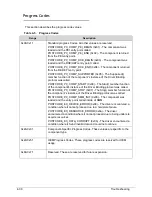
This section describes the progress code values.
Table 4-5. Progress Codes
Range
Description
0x00-0x1f
Standard progress Codes. All other values are reserved.
POSTCODE_PC_COMP_PEI_BEGIN (0x01) - The component was
loaded and the PEI entry point called.
POSTCODE_PC_COMP_PEI_END (0x02) - The component returned
from the PEI entry point.
POSTCODE_PC_COMP_DXE_BEGIN (0x03) - The component was
loaded and the DXE/UEFI entry point called.
POSTCODE_PC_COMP_DXE_END (0x04) - The component returned
from the DE/UEFI entry point.
POSTCODE_PC_COMP_SUPPORTED (0x05) - The Supported()
member function of the component's instance of the Driver Binding
protocol was called.
POSTCODE_PC_COMP_START (0x06) - The Start() member function
of the component's instance of the Driver Binding protocol was called.
POSTCODE_PC_COMP_STOP (0x07) - The Stop() member function of
the component's instance of the Driver Binding protocol was called.
POSTCODE_PC_COMP_SMM_INIT (0x08) - The component was
loaded and the entry point called inside of SMM.
POSTCODE_EC_DEVICE_ERROR (0x09) - The driver encountered a
condition where it cannot proceed due to a hardware failure.
POSTCODE_EC_RESOURCE_ERROR (0x0a) - The driver
encountered a condition where it cannot proceed due to being unable to
acquire resources.
POSTCODE_EC_DATA_CORRUPT (0x0b) - The driver encountered a
condition where it found invalid data and could not continue.
0x20-0x3f
Component-Specific Progress Codes. These values are specific to the
component type.
0x40-0x5f
OEM Progress Codes. These progress codes are reserved for OEM
usage.
0x60-0x7f
Reserved. These are reserved for future expansion.
Summary of Contents for Aspire 4560
Page 1: ... Aspire 4560 4560G SERVICEGUIDE ...
Page 10: ...x ...
Page 11: ...CHAPTER 1 Hardware Specifications ...
Page 14: ...1 4 ...
Page 51: ...CHAPTER 2 System Utilities ...
Page 67: ...CHAPTER 3 Machine Maintenance ...
Page 70: ...3 4 ...
Page 100: ...3 34 Machine Maintenance 4 Remove the USB board from the lower case Figure 3 44 USB Board ...
Page 109: ...Machine Maintenance 3 43 6 Remove the LCD module from the lower cover Figure 3 60 LCD Module ...
Page 162: ...3 96 Machine Maintenance ...
Page 163: ...CHAPTER 4 Troubleshooting ...
Page 193: ...CHAPTER 5 Jumper and Connector Locations ...
Page 200: ...5 8 Jumper and Connector Locations ...
Page 201: ...CHAPTER 6 FRU List ...
Page 202: ...6 2 Aspire 4560 4560G Exploded Diagram 6 4 Main Assembly 6 4 LCD Assembly 6 6 FRU List 6 7 ...
Page 217: ...CHAPTER 7 Model Definition and Configuration ...
Page 218: ...7 2 Aspire 4560 4560G 7 3 ...
Page 325: ...CHAPTER 8 Test Compatible Components ...
Page 326: ...8 2 Microsoft Windows 7 Environment Test 8 4 ...
Page 332: ...8 8 Test Compatible Components ...
Page 333: ...CHAPTER 9 Online Support Information ...
Page 334: ...9 2 Online Support Information 9 3 ...
Page 336: ...9 4 Online Support Information ...

