44
Chapter 2
Miscellaneous Utilities
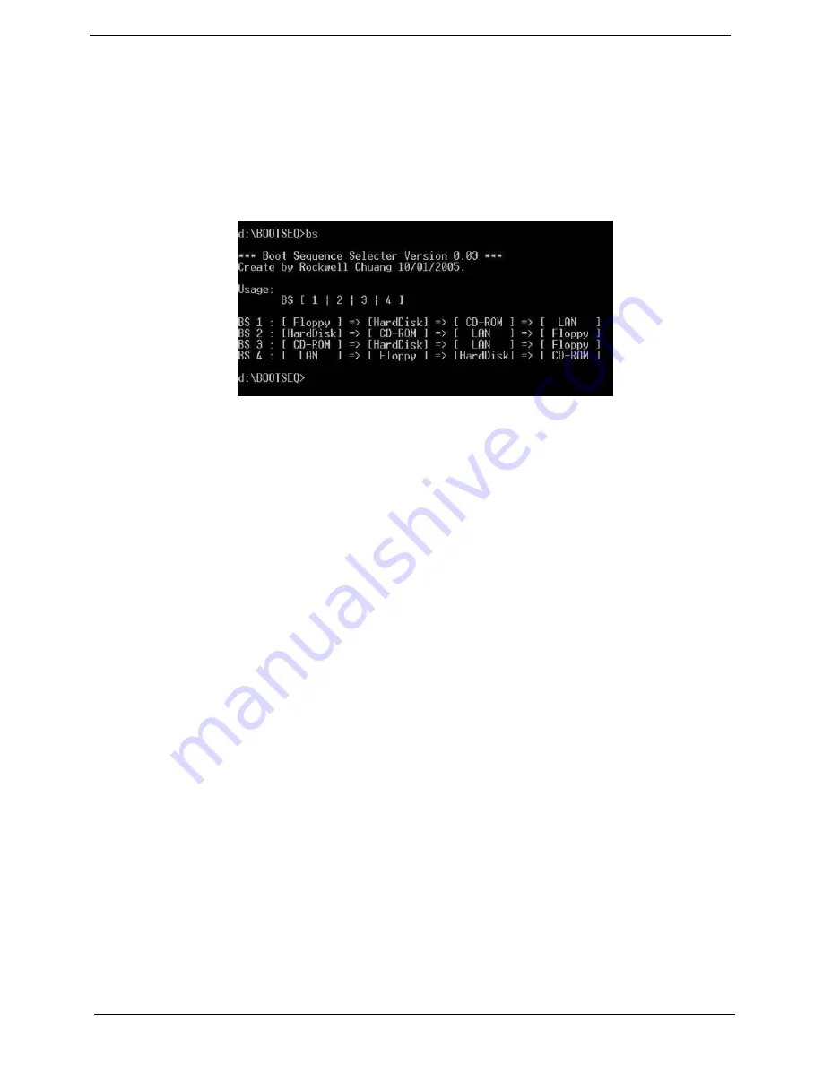
Using Boot Sequence Selector
Boot Sequence Selector allows the boot order to be changes without accessing the BIOS. To use Boot
Sequence Selector, perform the following steps:
1.
Enter into DOS.
2.
Execute
BS.exe
to display the usage screen.
3.
Select the desired boot sequence by entering the corresponding sequence, for example, enter BS2 to
change the boot sequence to HDD|CD ROM|LAN|Floppy.
Using DMITools
The DMI (Desktop Management Interface) Tool copies BIOS information to eeprom to be used in the DMI pool
for hardware management.
When the BIOS displays
Verifying DMI pool data
it is checking the table correlates with the hardware before
sending to the operating system (Windows, etc.).
To update the DMI Pool, perform the following steps:
1.
Enter into DOS.
2.
Execute
dmitools.exe
. The following messages show dmitools usage:
•
dmitools /r ==> Read dmi string from memory
•
dmitools /wm xxxx ==> Write manufacturer name to EEPROM (max. 16 characters)
•
dmitools /wp xxxx ==> Write product name to EEPROM (max. 16 characters)
•
dmitools /ws xxxx ==> Write serial number to EEPROM (max. 22 characters)
•
dmitools /wu xxxx ==> Write uuid to EEPROM (Ignore String)
•
dmitools /wa xxxx ==> Write asset tag to EEPROM (max. 32 characters)
NOTE:
The following write examples (2 to 5) require a system reboot to take effect
Example 1: Read DMI Information from Memory
Input:
dmitools /r
Output:
Manufacturer (Type1, Offset04h): Acer
Product Name (Type1, Offset05h): eMachines xxxxx
Serial Number (Type1, Offset07h): 01234567890123456789
UUID String (Type1, Offset08h): xxxxxxxx-xxxx-xxxx-xxxx-xxxxxxxxxxxx
Asset Tag (Type3, Offset04h): Acer Asstag
Summary of Contents for 4740G series
Page 6: ...VI ...
Page 10: ...X Table of Contents ...
Page 56: ...46 Chapter 2 ...
Page 63: ...Chapter 3 53 5 Carefully open the HDD Cover ...
Page 65: ...Chapter 3 55 5 Remove two 2 screws from the WLAN bracket and lift it clear of the device ...
Page 90: ...80 Chapter 3 5 Remove the TouchPad Bracket from the Upper Cover ...
Page 92: ...82 Chapter 3 Step Size Quantity Screw Type Media Board M2 5 3 2 ...
Page 97: ...Chapter 3 87 Step Size Quantity Screw Type Bluetooth Module M2 5 3 1 ...
Page 99: ...Chapter 3 89 7 Lift one edge of the mainboard as shown to remove it from the base ...
Page 107: ...Chapter 3 97 4 Lift the bezel away from the panel ...
Page 110: ...100 Chapter 3 4 Lift the LCD Panel out of the casing as shown ...
Page 117: ...Chapter 3 107 13 Ensure that the securing pin is properly located ...
Page 129: ...Chapter 3 119 ...
Page 134: ...124 Chapter 3 4 Turn the computer over Replace the fifteen screws on the bottom panel ...
Page 141: ...Chapter 3 131 4 Turn the computer over and replace the six 6 securing screws as shown ...
Page 186: ...176 Chapter 6 ...
Page 187: ...Chapter 6 177 ...
Page 208: ...Appendix A 198 ...
Page 214: ...204 Appendix B ...
Page 216: ...206 Appendix C ...