


146
Chapter 4
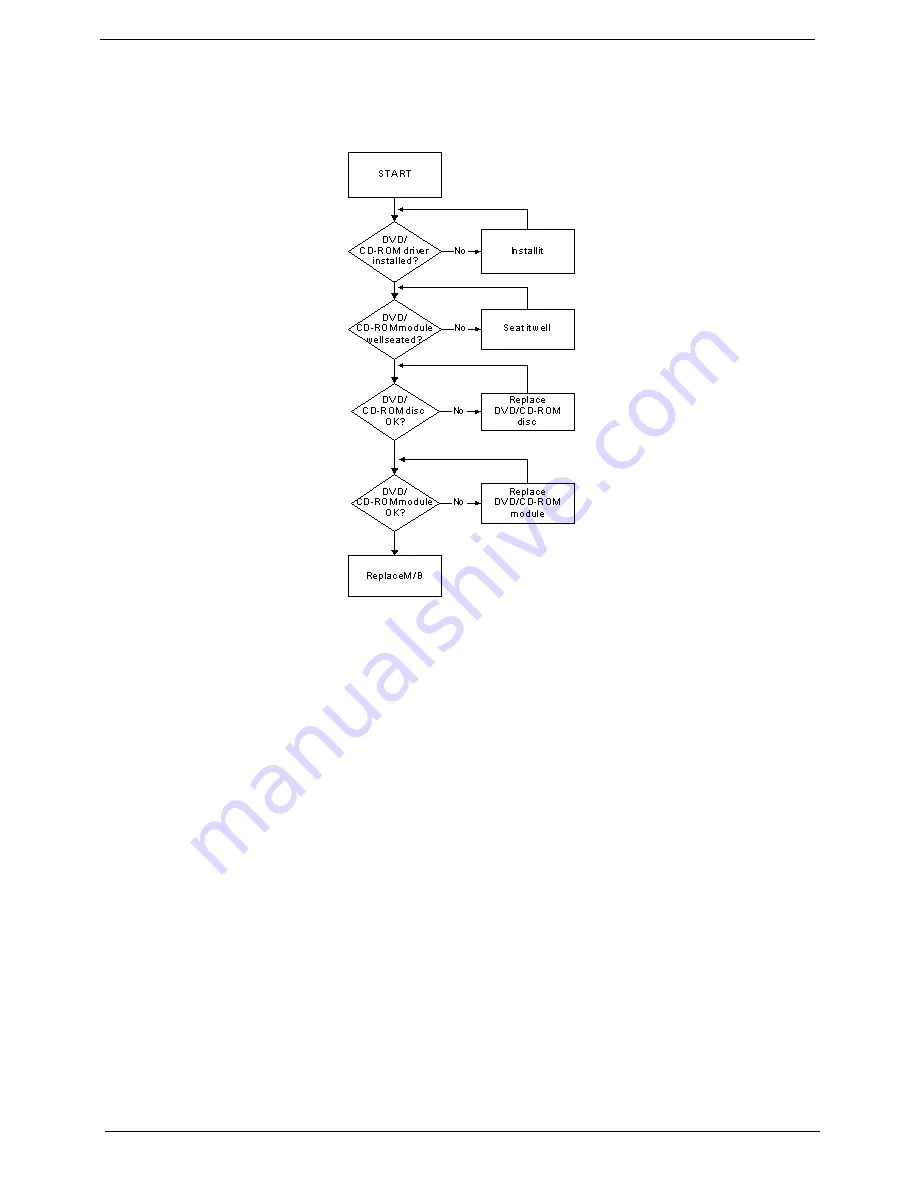
ODD Failure
If the
ODD
fails, perform the following actions one at a time to correct the problem. Do not replace a non-
defective FRUs:
ODD Not Operating Correctly
If the
ODD
exhibits any of the following symptoms it may be faulty:
•
Audio CDs do not play when loaded
•
DVDs do not play when loaded
•
Blank discs do not burn correctly
•
DVD or CD play breaks up or jumps
•
Optical drive not found or not active:
•
Not shown in My Computer or the BIOS setup
•
LED does not flash when the computer starts up
•
The tray does not eject
•
Access failure screen displays
•
The ODD is noisy
Perform the following general solutions one at a time to correct the problem.
1.
Reboot the computer and retry the operation.
2.
Try an alternate disc.
3.
Navigate to
Start
´
Computer
. Check that the ODD device is displayed in the
Devices
with
Removable
Storage
panel.
4.
Navigate to
Start
´
Control
Panel
´
System
and
Maintenance
´
System
´
Device
Manager
.
Summary of Contents for 4740G series
Page 6: ...VI ...
Page 10: ...X Table of Contents ...
Page 56: ...46 Chapter 2 ...
Page 63: ...Chapter 3 53 5 Carefully open the HDD Cover ...
Page 65: ...Chapter 3 55 5 Remove two 2 screws from the WLAN bracket and lift it clear of the device ...
Page 90: ...80 Chapter 3 5 Remove the TouchPad Bracket from the Upper Cover ...
Page 92: ...82 Chapter 3 Step Size Quantity Screw Type Media Board M2 5 3 2 ...
Page 97: ...Chapter 3 87 Step Size Quantity Screw Type Bluetooth Module M2 5 3 1 ...
Page 99: ...Chapter 3 89 7 Lift one edge of the mainboard as shown to remove it from the base ...
Page 107: ...Chapter 3 97 4 Lift the bezel away from the panel ...
Page 110: ...100 Chapter 3 4 Lift the LCD Panel out of the casing as shown ...
Page 117: ...Chapter 3 107 13 Ensure that the securing pin is properly located ...
Page 129: ...Chapter 3 119 ...
Page 134: ...124 Chapter 3 4 Turn the computer over Replace the fifteen screws on the bottom panel ...
Page 141: ...Chapter 3 131 4 Turn the computer over and replace the six 6 securing screws as shown ...
Page 186: ...176 Chapter 6 ...
Page 187: ...Chapter 6 177 ...
Page 208: ...Appendix A 198 ...
Page 214: ...204 Appendix B ...
Page 216: ...206 Appendix C ...


