


Chapter 1
15
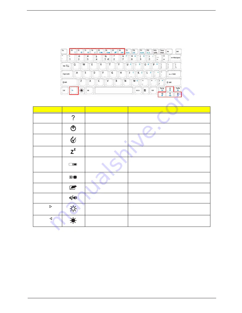
Hot Keys
The computer employs hotkeys or key combinations to access most of the computer’s controls like screen
brightness, volume output and the BIOS utility.
To activate hot keys, press and hold the <
Fn>
key before pressing the other key in the hotkey combination.
Hotkey
Icon
Function
Description
<Fn> + <F1>
Hotkey help
Displays help on hotkeys.
<Fn> + <F2>
Acer eSettings
Management
Launches Acer eSettings Management in Acer
Empowering Technology.
<Fn> + <F3>
Acer ePower
Management
Launches Acer ePower Management in Acer
Empowering Technology.
<Fn> + <F4>
Sleep
Puts the computer in Sleep mode.
<Fn> + <F5>
Display toggle
Switches display output between the display
screen, external monitor (if connected) and
both.
<Fn> + <F6>
Screen blank
Turns the display screen backlight off to save
power. Press any key to return.
<Fn> + <F7>
Touchpad toggle
Turns the internal touchpad on and off.
<Fn> + <F8>
Speaker toggle
Turns the speakers on and off.
<Fn> + < >
Brightness up
Increases the screen brightness.
<Fn> + < >
Brightness down
Decreases the screen brightness.
Summary of Contents for 4740G series
Page 6: ...VI ...
Page 10: ...X Table of Contents ...
Page 56: ...46 Chapter 2 ...
Page 63: ...Chapter 3 53 5 Carefully open the HDD Cover ...
Page 65: ...Chapter 3 55 5 Remove two 2 screws from the WLAN bracket and lift it clear of the device ...
Page 90: ...80 Chapter 3 5 Remove the TouchPad Bracket from the Upper Cover ...
Page 92: ...82 Chapter 3 Step Size Quantity Screw Type Media Board M2 5 3 2 ...
Page 97: ...Chapter 3 87 Step Size Quantity Screw Type Bluetooth Module M2 5 3 1 ...
Page 99: ...Chapter 3 89 7 Lift one edge of the mainboard as shown to remove it from the base ...
Page 107: ...Chapter 3 97 4 Lift the bezel away from the panel ...
Page 110: ...100 Chapter 3 4 Lift the LCD Panel out of the casing as shown ...
Page 117: ...Chapter 3 107 13 Ensure that the securing pin is properly located ...
Page 129: ...Chapter 3 119 ...
Page 134: ...124 Chapter 3 4 Turn the computer over Replace the fifteen screws on the bottom panel ...
Page 141: ...Chapter 3 131 4 Turn the computer over and replace the six 6 securing screws as shown ...
Page 186: ...176 Chapter 6 ...
Page 187: ...Chapter 6 177 ...
Page 208: ...Appendix A 198 ...
Page 214: ...204 Appendix B ...
Page 216: ...206 Appendix C ...


