


34
Chapter 2
Changing a Password
1.
Use the
↑
and
↓
keys to highlight the Set Supervisor Password parameter and press the
Enter
key. The
Set Password box appears.
2.
Type the current password in the Enter Current Password field and press
Enter
.
3.
Type a password in the Enter New Password field. Retype the password in the Confirm New Password
field.
4.
Press
Enter
. After setting the password, the computer sets the User Password parameter to “Set”.
5.
If desired, you can enable the Password on boot parameter.
6.
When you are done, press
F10
to save the changes and exit the BIOS Setup Utility.
If the verification is OK, the screen will display as following.
The password setting is complete after the user presses
Enter
.
If the current password entered does not match the actual current password, the screen will show you the
Setup Warning.
If the new password and confirm new password strings do not match, the screen displays the following
message.
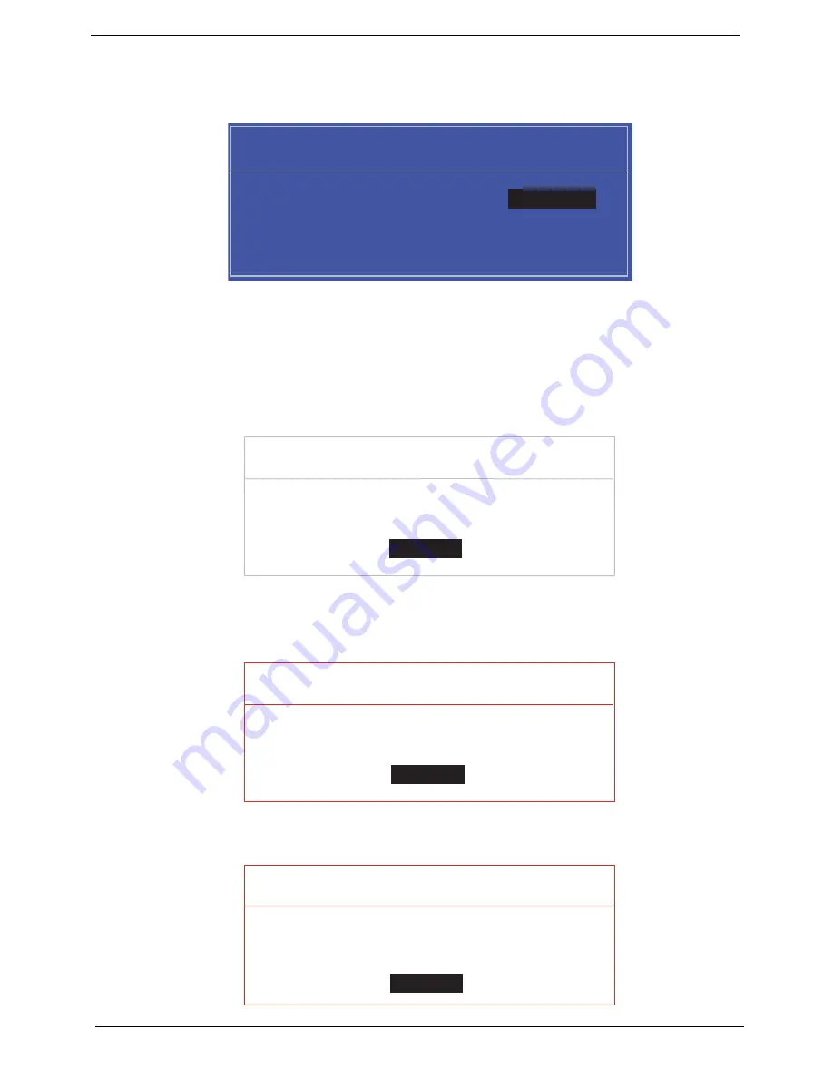
S e t S u p e r v i s o r P a s s w o r d
E n t e r C u r r e n t P a s s w o r d [ ]
[ ]
E n t e r N e w P a s s w o r d [ ]
C o n f i r m N e w P a s s w o r d [ ]
[ ]
S e t u p N o t i c e
C h a n g e s h a v e b e e n s a v e d .
[ C o n t i n u e ]
[
C o n t i n u e
]
S e t u p W a r n i n g
I n v a l i d P a s s w o r d .
[ C o n t i n u e ]
[
C o n t i n u e
]
S e t u p W a r n i n g
P a s s w o r d s d o n o t m a t c h .
R e - e n t e r p a s s w o r d .
[ C o n t i n u e ]
[
C o n t i n u e
]
Summary of Contents for 4740G series
Page 6: ...VI ...
Page 10: ...X Table of Contents ...
Page 56: ...46 Chapter 2 ...
Page 63: ...Chapter 3 53 5 Carefully open the HDD Cover ...
Page 65: ...Chapter 3 55 5 Remove two 2 screws from the WLAN bracket and lift it clear of the device ...
Page 90: ...80 Chapter 3 5 Remove the TouchPad Bracket from the Upper Cover ...
Page 92: ...82 Chapter 3 Step Size Quantity Screw Type Media Board M2 5 3 2 ...
Page 97: ...Chapter 3 87 Step Size Quantity Screw Type Bluetooth Module M2 5 3 1 ...
Page 99: ...Chapter 3 89 7 Lift one edge of the mainboard as shown to remove it from the base ...
Page 107: ...Chapter 3 97 4 Lift the bezel away from the panel ...
Page 110: ...100 Chapter 3 4 Lift the LCD Panel out of the casing as shown ...
Page 117: ...Chapter 3 107 13 Ensure that the securing pin is properly located ...
Page 129: ...Chapter 3 119 ...
Page 134: ...124 Chapter 3 4 Turn the computer over Replace the fifteen screws on the bottom panel ...
Page 141: ...Chapter 3 131 4 Turn the computer over and replace the six 6 securing screws as shown ...
Page 186: ...176 Chapter 6 ...
Page 187: ...Chapter 6 177 ...
Page 208: ...Appendix A 198 ...
Page 214: ...204 Appendix B ...
Page 216: ...206 Appendix C ...


