


32
Chapter 2
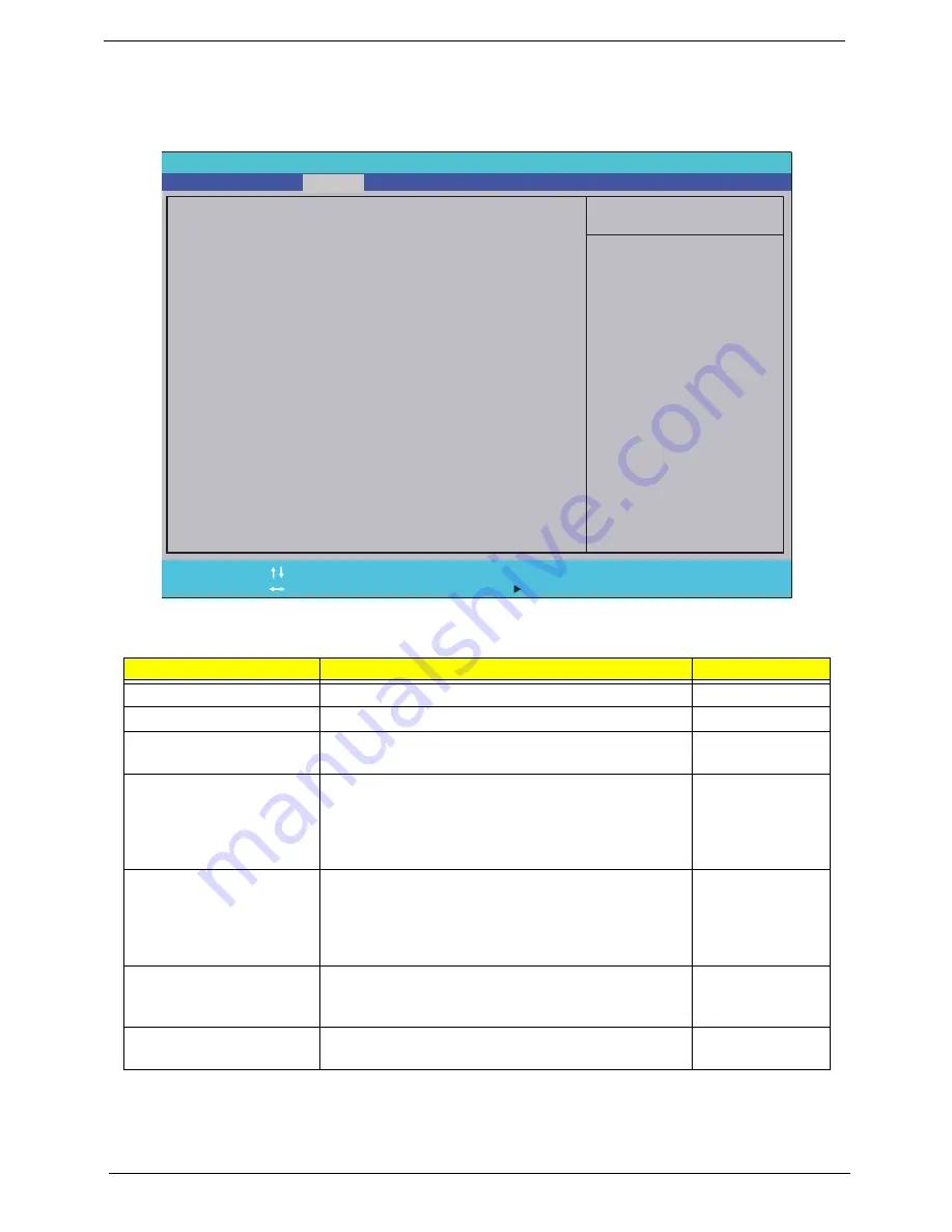
Security
The Security screen contains parameters that help safeguard and protect your computer from unauthorized
use.
The table below describes the parameters in this screen. Settings in
boldface
are the default and suggested
parameter settings.
NOTE:
When you are prompted to enter a password, you have three tries before the system halts. Don’t forget
your password. If you forget your password, you may have to return your notebook computer to your
dealer to reset it.
Parameter
Description
Option
Supervisor Password Is
Shows the setting of the Supervisor password
Clear
or Set
User Password Is
Shows the setting of the user password.
Clear
or Set
HDD Password Is
Shows the setting of the hard disk password.
Clear, Set, or
Frozen
Set Supervisor Password
Press Enter to set the supervisor password. When
set, this password protects the BIOS Setup Utility
from unauthorized access. The user can not either
enter the Setup menu nor change the value of
parameters.
N/A
Set User Password
Press Enter to set the user password. When user
password is set, this password protects the BIOS
Setup Utility from unauthorized access. The user can
enter Setup menu only and does not have right to
change the value of parameters.
N/A
Set HDD Password
Press Enter to set the Hdd password. When Hdd
password is set, this password protects the Hdd from
unauthorized access.
N/A
Power on password
Defines whether a password is required or not while
the system powers on.
Disabled
or
Enabled
I t e m S p e c i f i c H e l p
I n s t a l l o r C h a n g e t h e
p a s s w o r d a n d t h e l e n g t h
o f p a s s w o r d m u s t b e
g r e a t e r t h a n o n e w o r d .
F 1
E S C
H e l p
E x i t
S e l e c t I t e m
S e l e c t M e n u
C h a n g e Va l u e s
S e l e c t
S u b M e n u
E n t e r
F 9
F 1 0
S e t u p D e f a u l t
S a v e a n d E x i t
C l e a r
C l e a r
C l e a r
[ D i s a b l e d ]
C l e a r
C l e a r
C l e a r
[ D i s a b l e d ]
S u p e r v i s o r P a s s w o r d I s :
U s e r P a s s w o r d I s :
H D D P a s s w o r d I s :
S e t S u p e r v i s o r P a s s w o r d
S e t U s e r P a s s w o r d
S e t H D D P a s s w o r d
P a s s w o r d o n B o o t
S u p e r v i s o r P a s s w o r d I s :
U s e r P a s s w o r d I s :
H D D P a s s w o r d I s :
S e t S u p e r v i s o r P a s s w o r d
S e t U s e r P a s s w o r d
S e t H D D P a s s w o r d
P a s s w o r d o n B o o t
F 5 / F 6
I n s y d e H 2 0 S e t u p U t i l i t y R e v . 3 . 5
Information
Main
Boot
Exit
Security
Summary of Contents for 4740G series
Page 6: ...VI ...
Page 10: ...X Table of Contents ...
Page 56: ...46 Chapter 2 ...
Page 63: ...Chapter 3 53 5 Carefully open the HDD Cover ...
Page 65: ...Chapter 3 55 5 Remove two 2 screws from the WLAN bracket and lift it clear of the device ...
Page 90: ...80 Chapter 3 5 Remove the TouchPad Bracket from the Upper Cover ...
Page 92: ...82 Chapter 3 Step Size Quantity Screw Type Media Board M2 5 3 2 ...
Page 97: ...Chapter 3 87 Step Size Quantity Screw Type Bluetooth Module M2 5 3 1 ...
Page 99: ...Chapter 3 89 7 Lift one edge of the mainboard as shown to remove it from the base ...
Page 107: ...Chapter 3 97 4 Lift the bezel away from the panel ...
Page 110: ...100 Chapter 3 4 Lift the LCD Panel out of the casing as shown ...
Page 117: ...Chapter 3 107 13 Ensure that the securing pin is properly located ...
Page 129: ...Chapter 3 119 ...
Page 134: ...124 Chapter 3 4 Turn the computer over Replace the fifteen screws on the bottom panel ...
Page 141: ...Chapter 3 131 4 Turn the computer over and replace the six 6 securing screws as shown ...
Page 186: ...176 Chapter 6 ...
Page 187: ...Chapter 6 177 ...
Page 208: ...Appendix A 198 ...
Page 214: ...204 Appendix B ...
Page 216: ...206 Appendix C ...


