Chapter 4
155
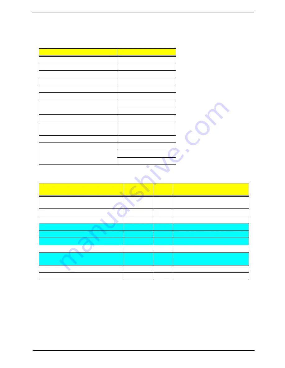
Post Codes
These tables describe the POST codes and descriptions during the POST.
Post Code Range
SEC Phase POST Code Table
NOTE:
The color bar items indicate 3rd party related functions that are platorm dependent.
Phase
POST Code Range
SEC
0x01 - 0x0F
PEI
0x70 - 0x9F
DXE
0x40 - 0x6F
BDS
0x10 - 0x3F
SMM
0xA0 - 0xBF
S3
0xC0 - 0xCF
ASL
0x51 – 0x55
0xE1 – 0xE4
PostBDS
0xF9 – 0xFE
InsydeH2ODDT™
Reserve
0xD0 – 0xD7
OEM Reserve
0xE8 – 0xEB
Reserved
0xD8 – 0xE0
0xE5 – 0xE7
0xEC – 0xF8
Functionality Name (Include\
PostCode.h)
Phase
Post
Code
Description
SEC_SYSTEM_POWER_ON
SEC
1
CPU power on and switch to
Protected mode
SEC_BEFORE_MICROCODE_PATCH
SEC
2
Patching CPU microcode
SEC_AFTER_MICROCODE_PATCH
SEC
3
Setup Cache as RAM
SEC_ACCESS_CSR
SEC
4
PCIE MMIO Base Address initial
SEC_GENERIC_MSRINIT
SEC
5
CPU Generic MSR initialization
SEC_CPU_SPEEDCFG
SEC
6
Setup CPU speed
SEC_SETUP_CAR_OK
SEC
7
Cache as RAM test
SEC_FORCE_MAX_RATIO
SEC
8
Tune CPU frequency ratio to
maximum level
SEC_GO_TO_SECSTARTUP
SEC
9
Setup BIOS ROM cache
SEC_GO_TO_PEICORE
SEC
0A
Enter Boot Firmware Volume
Summary of Contents for 4740G series
Page 6: ...VI ...
Page 10: ...X Table of Contents ...
Page 56: ...46 Chapter 2 ...
Page 63: ...Chapter 3 53 5 Carefully open the HDD Cover ...
Page 65: ...Chapter 3 55 5 Remove two 2 screws from the WLAN bracket and lift it clear of the device ...
Page 90: ...80 Chapter 3 5 Remove the TouchPad Bracket from the Upper Cover ...
Page 92: ...82 Chapter 3 Step Size Quantity Screw Type Media Board M2 5 3 2 ...
Page 97: ...Chapter 3 87 Step Size Quantity Screw Type Bluetooth Module M2 5 3 1 ...
Page 99: ...Chapter 3 89 7 Lift one edge of the mainboard as shown to remove it from the base ...
Page 107: ...Chapter 3 97 4 Lift the bezel away from the panel ...
Page 110: ...100 Chapter 3 4 Lift the LCD Panel out of the casing as shown ...
Page 117: ...Chapter 3 107 13 Ensure that the securing pin is properly located ...
Page 129: ...Chapter 3 119 ...
Page 134: ...124 Chapter 3 4 Turn the computer over Replace the fifteen screws on the bottom panel ...
Page 141: ...Chapter 3 131 4 Turn the computer over and replace the six 6 securing screws as shown ...
Page 186: ...176 Chapter 6 ...
Page 187: ...Chapter 6 177 ...
Page 208: ...Appendix A 198 ...
Page 214: ...204 Appendix B ...
Page 216: ...206 Appendix C ...