2 Lot Processing
2-15
2.4.2 Manual
Alignment
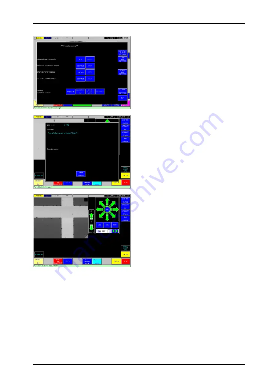
To manually align the wafers instead of automatic
alignment, touch the <Operation Settings> button on the
Prober Status or Lot Information/Loader Status screen to
display the [Operation Settings] screen.
Select 'Manual’ for "Alignment Mode”.
When the position and thickness measurement is
complete for each wafer on the chuck, the chuck is moved
to below the alignment camera. The die pattern from the
left edge of the wafer will be displayed on the screen
(shown on left).
"Push <DATA-IN> SW at UNIQUE POINT!!” is displayed
on the screen. Locate a unique point in the die pattern, use
the arrow keys to align this point with the crosshair, and
touch the <DATA-IN> button.
The chuck moves and the die pattern from the right edge
of the wafer will be displayed on the screen. Locate a
unique point along the same die row as the first point, use
the arrow keys to align this point with the crosshair, and
touch the <DATA-IN> button. The chuck rotates so that the
two data-in points are on a line parallel to the X axis. The
left edge of the wafer is brought under the camera once
again.
Use the arrow keys to adjust the angle of the wafer until
both data-in points are aligned with the crosshair, and
touch the <Theta Angle Finish> button.
Post-processing for manual alignment
For wafers of devices that can usually be automatically aligned but had to be manually aligned
for one reason or another, automatic probe-pad alignment can still be performed. In this case,
follow the instructions on the screen to (1) perform teaching of the street position, and (2)
reconfirm the registered pad locations.


