background image

27

9 - REGOLAZIONE ELETTRONICA

9 - ELECTRONIC CONTROL

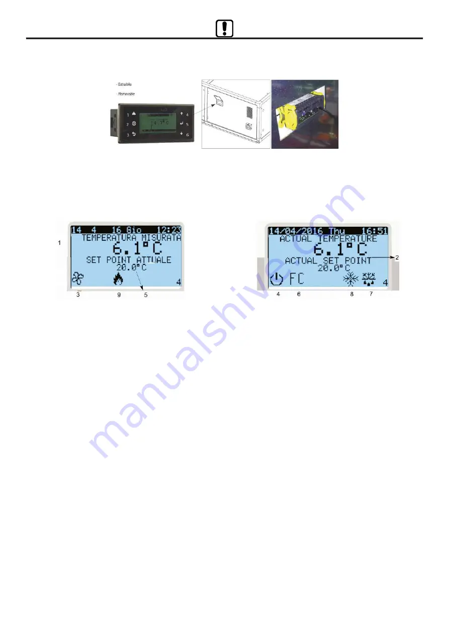
9.2 INTERFACCIA UTENTE

9.2 CONTROL PANEL

Legenda tasti

Meaning of buttons

1.

Tasto “Allarme” per visualizzazione/reset allarme

2.

Tasto “Prg” per l’accesso al menù principale

3.

Tast “Esc” per l’uscita dal menù

4.

Tasto “Up” incremento parametro

5.

Tasto “Enter” per l’accesso ai menù

6.

Tasto “Down” decremento parametro

1.

Alarm visualization/Alarm reset

2.

Setting enter

3.

Setting exit

4.

Parameter list up-flow/Set value increasing

5.

Sub list enter/Set value

6.

Parameter list down-flow/Set value decreasing

1.

Visualizzazione ora/giorno corrente

2.

Visualizzazione temperatura ripresa

3.

Unità operativa

4.

Unità spenta

5.

Set point attuale

6.

Modalità free cooling attiva

7.

Modalità sbrinamento attiva

8.

Modalità raffreddamento attiva

9.

Modalità riscaldamento attiva

1.

Current time/day

2.

Return air temperature

3.

Unit running

4.

Unit off

5.

Actual set point

6.

Free cooling mode on

7.

Defrost mode on

8.

Cooling mode on

9.

Heating mode on

9.3 PROGRAMMAZIONE

9.3 SETTING

La programmazione dei parametri avviene tramite il menù

assistenza, cui si accede premendo il tasto di programmazione

(simbolo circoletto) posto in posizione centrale nella parte

sinistra del display. All’apparire dei menù contraddistinti dalle

lettere da A ad H sarà possibile selezionare la voce desiderata

spostandosi con le frecce Su/Giù e premendo il tasto Enter in

corrispondenza della voce desiderata.

Menu A:

On/Off Unità

Accedendo a questo menù è possibile accendere/spegnere

l’unità localmente ed escludere/includere il comando locale per

permettere l’accensione/spegnimento da comando remoto, da

supervisione o da fascia oraria.

Fino a che il comando locale resta incluso, esso avrà sempre

precedenza su tutte le interfacce esterne.

Per escludere il comando locale occorre selezionare SI nella

voce “Escludi comando locale”.

Nei modelli dotati di ventilatori EC la modifica della velocità o

della portata d’aria (dalla taglia 100 in poi) avviene premendo il

tasto freccia in basso dalla pagina principale. Appare a questo

punto la pagina dove sono indicati i due ventilatori di mandata e

ripresa con il relativo valore di velocità o portata d’aria espresso

in percentuale. Per modificare tale valore portarsi con il cursore

lampeggiante su di esso e modificare il valore con i tasti freccia

in alto / freccia in basso e confermare con “Enter”.

Setting of parameters can be done through the Service menu,

that can be reached by pushing the programming button (with

round circle symbol), which is located in central position at the

left side of the screen. When the menu marked with the letters

from A to H appears, the required entry can be selected by

moving with the arrows Up/Down and pushing the button “Enter”

corresponding to the required entry.

Menu A:

Unit On/Off

By entering this menu it is possible to locally turn on/turn off the

unit and to exclude/include the local control to allow the turning

on/off through remote control, through monitoring or time slot.

The local control will have the priority on all the other external

interfaces as long as it remains included.

To exclude the local control, select “YES” in the entry “Exclude

local control”.

In models with EC fans, changing the speed or airflow (from

size 100 upwords) happens by pressing the Down arrow key on

the main page.

At this point, the page where the two delivery and recovery fans

are indicated with the relative speed or air flow rate expressed

as a percentage. To change that value, move the cursor over it

and change the value with the up / down arrow keys and confirm

with “Enter”.

pag.28 - Manuale di installazione, Uso e Manutenzione -

Installation, Use and Maintenance Manual

Summary of Contents for CFR HP 100

Page 1: ...PE 35 450 Sistema di climatizzazione e deumidificazione con rinnovo dell aria e compressore termodinamico di supporto Air conditioning and dehumidification system with air renewal and compressor therm...

Page 2: ...CI 9 REGOLAZIONE ELETTRONICA 10 CONTROLLI PRIMA DELL AVVIAMENTO 11 MANUTENZIONE ORDINARIA 12 LOCALIZZAZIONE DEI GUASTI 13 SMALTIMENTO 14 PARTI DI RICAMBIO 1 SYMBOLS USED 2 WARNINGS AND GENERAL RULES 3...

Page 3: ...rle pi evidenti The most important information concerning safety and proper use of the machine are accompanied by some symbols to make them highly visible 2 AVVERTENZE E REGOLE GENERALI 2 WARNINGS AND...

Page 4: ...vo il produttore si riserva di apportare qualsiasi modifica senza preavviso As our Company is constantly involved in the continuous improvement of its production aesthetic characteristics and dimensio...

Page 5: ...TIFICATION OF THE UNIT PER EVENTUALI RICHIESTE DI INFORMAZIONI NECESSARIO RIVOLGERSI ALLA SEDE COMUNICANDO IL NUMERO DI SERIE DELL UNIT WHEN CONTACTING THE OFFICE FOR ANY INFORMATION ENQUIRIES PLEASE...

Page 6: ...ling pag 7 Manuale di installazione Uso e Manutenzione Installation Use and Maintenance Manual This manual describes the rules for the transportation the installation the use and the maintenance of th...

Page 7: ...et metal outer skin 45 kg m3 density foamed polyurethane as heat and sound insulation Filtering sections at both air intakes complete with efficiency cell filters ISO 16890 COARSE 55 G4 EN779 extracta...

Page 8: ...3 16 6 COP globale Unit COP 5 W W 10 3 8 9 9 4 9 6 12 6 10 6 13 8 Temperatura immissione Supply air temperature C 23 5 23 2 24 1 23 0 21 5 23 0 19 0 PRESTAZIONI IN RAFFRESCAMENTO 4 COOLING CAPACITIES...

Page 9: ...nt configurations 01 02 1S 2S as shown below each of which to be specified at ordering ORIENTAMENTO TIPO 01 CONFIGURATION TYPE 01 Tipo standard Standard type ORIENTAMENTO TIPO 02 CONFIGURATION TYPE 02...

Page 10: ...A1 mm 1495 1495 1795 1795 1995 1995 2195 C1 mm 1294 1294 1494 1494 1744 1744 1944 D mm 300 300 400 400 500 500 600 E mm 210 210 210 310 410 510 510 F mm 232 232 233 233 299 332 332 F1 mm 458 458 703...

Page 11: ...i mandata Le caratteristiche tecniche sono indicate nella tabella seguente The electric heater contains a filament type element which limits pressure drop and it is mounted inside the unit Safety ther...

Page 12: ...ut water te perature 7 12 C SE I E C BATTERIA AUSI IARIA AD ACQUA SBFR Tr va spa i i app sit du i a iera i cata c ibe tata c ega bi e a u it attravers id ea ca a i a i e essa pu essere i piega ta per...

Page 13: ...ase of dirty filter as max air pressure drop to be set the remote control panel informs the user by specific alarm code on the display ATTACCO CIRCOLARE SPC1 ROUND AIR DUCT ADAPTOR SPC1 Realizzato in...

Page 14: ...e cab e t supp ied by the a ufacturer but by the i sta er A the i f r ati s a d the features f the ai disp ay b ard are repeated the re te disp ay The re te disp ay is suitab e f r wa i sta ati a the...

Page 15: ...THE SUPPLY AIR DUCT SCHEDA INTERFACCIA PROTOCOLLO MODBUS SCMB MODBUS PROTOCOL INTERFACE PCB SCMB Modulo inseribile nell unit logica di controllo gi cablata al quadro elettrico di bordo il quale consen...

Page 16: ...tors external air is mixed expulsion air after heat recovery in order to reduce defrost cycle and the heat pump working up to 20 C air temperature N B Disponibile solo con orientamento 01 o 01S ATTENT...

Page 17: ...ati dal trasporto Gli eventuali danni devono essere debitamente comunicati al vettore e specificati nella clausola di riserva riportata nella bolla di accompagnamento When receiving the goods before u...

Page 18: ...are quanto raccomanda il produttore di tali prodotti Prima di mettere in funzione l unit controllare la perfetta integrit dei vari componenti e dell intero impianto Evitare assolutamente di toccare le...

Page 19: ...o in special modo in condizioni di esercizio oltre i limiti operativi indicati a catalogo Posizionare l unit su di una struttura solida adeguata al peso della macchina interporre sempre opportuni sist...

Page 20: ...nd air duct if metallic Avoid air supplied directly into the room and air expelled directly into the atmosphere prefer short or long duct connection Compare unit sound level to the required room acous...

Page 21: ...do lungo tutto il perimetro i del telaio in alluminio indicato dal perimetro grigio nella figura 4 Tramite le due staffe forate posizionare l accessorio su di una struttura solida adeguata al suo peso...

Page 22: ...cables arranged on the unit side through the holes see the picture below Connect the cables to the terminal block see the electrical drawing at chapter 8 fig 5 Una volta ancorata la sezione RMS alla s...

Page 23: ...t damage to the copper collectors in the coil The route of the pipes must be studied in a way not to create obstacles if the unit coil is extracted Water inlet outlet must be such to allow countercurr...

Page 24: ...hemi elettrici a corredo dell unit e di questo manuale fig 8 8A Usare i passacavo presenti sul pannellino frontale per collegare il quadro elettrico interno Before carrying out any service check that...

Page 25: ...25 8 COLLEGAMENTI ELETTRICI 8 ELECTRIC CONNECTIONS fig 8A pag 26 Manuale di installazione Uso e Manutenzione Installation Use and Maintenance Manual...

Page 26: ...tegrazione termica ventilatori on Thermal integration fan on 813 N NO4 Uscita digitale Digital output Preriscaldo elettrico Electric preheating 814 N NO5 Uscita digitale Digital output Valvola inversi...

Page 27: ...facce esterne Per escludere il comando locale occorre selezionare SI nella voce Escludi comando locale Nei modelli dotati di ventilatori EC la modifica della velocit o della portata d aria dalla tagli...

Page 28: ...is equipped with a regulation logic that controls all the actuators to produce hot cold air by comparing the different temperature probes By using this menu entrym it is possible to make the unit work...

Page 29: ...logico 03 temperatura aria espulsa AI4 Ingresso analogico 04 temperatura aria mandata AI5 Ingresso analogico 05 temperatura aspirazione compressore AI6 Ingresso analogico 06 pressione aspirazione comp...

Page 30: ...ecorder G Assistenza Tecnica G Service level a Cambio lingua a Language set Lingua selezionabile Selectable language G Assistenza Tecnica G Service level b Informazioni b Information Gb01 Gb02 Info su...

Page 31: ...nza tecnica G Service level f Param Assistenza c Termoregolazione f Service setting c Regulation Setpoint temperatura sbrinamento Defrost setpoint 10 10 Differenziale sbrinamento Defrost hysteresys Gf...

Page 32: ...tton to the left to enter the menu 10 Enter to menu A On Off unit 11 Press YES for the voice Exclusion of local command At this point it s possible to command the input unit see circuit diagram for th...

Page 33: ...t 9 7 SUPERVISIONE PROTOCOLLO MODBUS RTU 9 7 BUILDING MANAGEMENT SYSTEM MODBUS RTU PROTOCOL Con accessorio SCMB l unit agisce da slave modbus I parametri di configurazione della porta di comunicazione...

Page 34: ...an 211 Modo funzionamento Running mode 0 R W 0 Heat Recovery 1 AHU 212 Tipo sbrinamento Defrost mode 0 R W 0 not active 1 electric 2 speed reduction 3 Recirculation 213 Velocit ventilatore mandata tre...

Page 35: ...atus of thermal protection digital input 15 Ingresso Allarme Alarm input R Status of Alarm digital input 16 Riservato Reserved R 17 Riservato Reserved R 18 Riservato Reserved R 19 Riservato Reserved R...

Page 36: ...with consequent worsening of room comfort Before carrying out any maintenance make sure that basic unit and its possible options are not and can not be powered anyway therefore turn off in advance We...

Page 37: ...ll be free to run without any vibration or noise and electrical connections shall be intact and well tightened CIRCUITO FRIGORIFERO Controllare visivamente il circuito frigorifero accedendo dal relati...

Page 38: ...operations shall be carried out by authorized service point only 12 LOCALIZZAZIONE DEI GUASTI 12 IDENTIFYNG BREAKDOWNS 12 1 GUIDA RICERCA GUASTI 12 1 TROUBLESHOOTING GUIDE Anomalia probabile causa po...

Page 39: ...io sostituire la sonda Check probe and sustitute it if necessary Al9 Sonda B08 rotta o sconnessa Probe B08 fault or disconnected Controllare il collegamento e se necessario sostituire la sonda Check p...

Page 40: ...hi Dirty filters Procedere alla pulizia dei filtri Clean filters Al30 Allarme memoria estesa Internal memory alarm Allarme memoria controllore Internal controller memory fault Cambiare il controllore...

Page 41: ...ust air DX coil BTAEGD0260J02NO0 HP 100 1 Ventilatore standard Standard fan VTDDM080741T0420 1 Ventilatore EC EC motor fan VTDDM0807ECP0400 2 Recuperatore Recovery exchanger PR4900360339A100 3 Filtro...

Page 42: ...tandard fan VTDDM101042A0800 1 Ventilatore EC EC motor fan VTDDM1010ECP0800 2 Recuperatore Recovery exchanger PR6000590339A320 3 Filtro standard G4 G4 standard filter CF0OZ55760098000 4 Quadro elettri...

Page 43: ...43...

Page 44: ...itolo puramente indicativo la A2B Accorroni E G S r l si riserva di apportare eventuali modi che senza alcun preavviso web site www accorroni it e mail a2b accorroni it A2B Accorroni E G s r l Via d A...

Reviews: