15
For more cool Wattage products visit our website at http://watt-age.globalhobby.com
❑
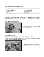
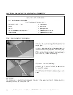
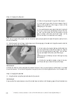
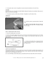
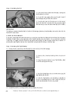
Using a modeling knife, cut away the covering material
from within the outline. Remove the covering from the bot-
tom, front portion of the vertical stabilizer, too.
IMPORTANT
Removing the covering will result in a stronger bond for the
glue.
Step 2: Mounting the Vertical Stabilizer
❑
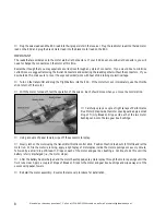
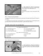
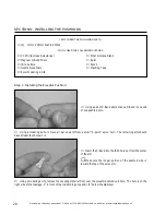
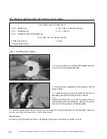
Apply a generous amount of 5 minute epoxy to the gluing surfaces of the stabilizer and to the inside of the stabilizer
mounting slot.
❑
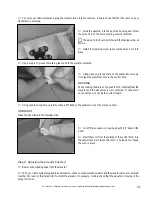
Set the stabilizer into place and realign it, double checking all of your measurements once more before the epoxy sets
up. Quickly remove the excess epoxy and hold the stabilizer in place until the epoxy has set up.
❑
# 1 Phillips Head Screwdriver
❑
Excel Modeling Knife
❑
Electric Drill
❑
1/16" Drill Bit
YOU'LL NEED THE FOLLOWING PARTS:
❑
{2} Prebent Main Gear Wires
❑
{2} Main Gear Wheels
❑
{2} Nylon Landing Gear Straps
SECTION 6: INSTALLING THE LANDING GEAR
❑
{4} 3mm x 10mm Wood Screws
❑
{2} 3mm Nylon Spacers
❑
{2} 3mm Wheel Collars w/Set Screws
YOU'LL NEED THE FOLLOWING SUPPLIES:
❑
Ernst Airplane Stand
❑
Ruler
❑
Pencil
❑
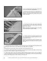
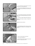
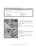
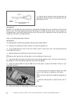
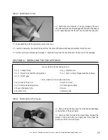
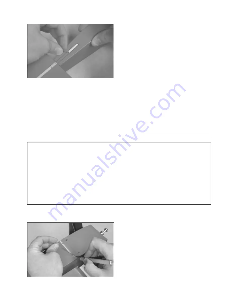
Using a modeling knife, cut away the covering material
from over the landing gear slot in the bottom of the fuselage.
The slot is 3/16" wide, 2-3/4" long and 3/8" behind the hatch
cover.
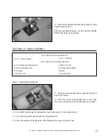
Step 1: Installing the Landing Gear Wires


