www.absgroup.com
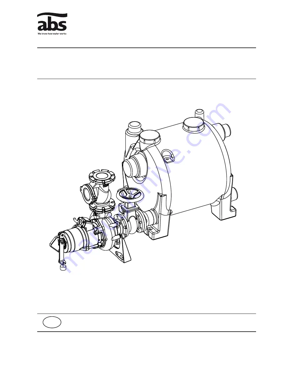
ABS lifting station Sanimat
1030-00
15970299GB (10/2006)
Installation and Operating Instructions
GB
Page 1: ...www absgroup com ABS lifting station Sanimat 1030 00 15970299GB 10 2006 Installation and Operating Instructions GB...
Page 2: ...4 Discharge Line 8 4 5 Installation of the submersible pump 9 4 5 1 Mounting of the volute support 9 4 5 2 Installation of the pump head support 9 4 6 Level Control 10 4 7 Installation of the control...
Page 3: ...12056 1 2 Technical Data Maximum noise level 70 dB 1 3 Nameplate We recommend that you record the data from the original nameplate on the nameplate illustration below and maintain it together with you...
Page 4: ...sible pump is noise absorbing Volute support Inspection opening above Sanimat 3701 2 off Inflow ports DN 100 150 Controls Control line for the level control Vent port Inflow ports ON 100 150 height 70...
Page 5: ...ttom plate with waved shearing inlet open ABS channel type impeller and volute All hydraulic parts have been manufactured from Cast Iron GG 25 The sewage entering by the inlet port is collected in the...
Page 6: ...d 1 Vent Pipe DN 70 above roof level 12 Hand membrane pump connection 2 Control unit with level control system 13 Backwash loop with lowest point above the backwash level 3 Power supply 14 Discharge l...
Page 7: ...terials The inlet lines must be laid in such a manner that there is a continuous fall of the prescribed magnitude to the inlet ports of the collection tank NOTE When installing lifting stations the no...
Page 8: ...be installed in compliance with the relevant regulations DIN 1986 100 and EN 12056 applies in particular to the following The discharge line should be fitted with a backwash loop 180 bend located abov...
Page 9: ...onnection 8 with clamp 7 to the pump connection port of the collection tank 1 Press the volute support 6 into the flexible connector 8 and mark the position of the volute support 6 on the floor Remove...
Page 10: ...S S17 S26 Place the vibration damper 6 at the pump head support Screw the pump head support 5 into the pump head using socket head screw 4 Adjust the vibration damper 6 in such a manner that the rubbe...
Page 11: ...fferent control box models exist Please check the wiring diagram instruction manual in the control box 4 8 Electrical Connection c Before commissioning an expert should check that one of the necessary...
Page 12: ...iring with Temperature Limiter Figure 13 Single Phase Wiring with Temperature Limiter 1015 00 1018 00 Figure 14 Three Phase Wiring with Temperature Limiter DI Figure 15 Single Phase Wiring with Temper...
Page 13: ...es 4 11 Installation of the accessories 4 11 1 Installation of the Hand Membrane Pump wall mounted 1086 00 Figure 17 Installation of hand membrane pump ATTENTION The discharge line 1 from the hand mem...
Page 14: ...rated with the selector switch in position Auto 6 Maintenance c Before commencing any maintenance work the unit should be completely disconnected from the mains by a qualified person and care should b...
Page 15: ...gular inspection and care is recommended to ensure a long service life NOTE The ABS service organisation would be pleased to advise you on any applications you may have and to assist you in solving yo...
Page 16: ...ABS Production Wexford Ltd Clonard Road Wexford Ireland Tel 353 53 91 63 200 Fax 353 53 91 42335 www absgroup com...