


29
Electrical connection of the wallbox
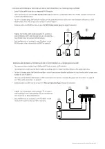
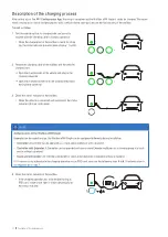
Proceed as follows to connect the power line inside the wallbox:
1
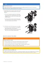
Shorten the power line to the required length for the terminal
block using a stripping tool / stripping pliers.
2
Remove the sheath from the power line with the stripping
tool.
3
Remove the insulation of the individual conductors to a length
of 16 mm.
x
End ferrules must be fitted on flexible conductors.
16 mm
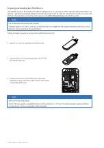
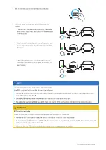
4
Insert the individual conductors of the power supply cable
into the respective terminals and tighten them using the
Phillips screwdriver (torque: 2.5 Nm).
x
Use the diagram on the communication module as a guide
to allocate the individual conductors.
x
End ferrules must be fitted on flexible conductors.
L1
L2
L3
N
PE
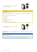
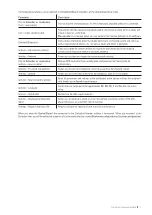
NOTE
1-phase connection of the Wallbox eM4 Single
If you want to operate the Wallbox eM4 Single in a 1-phase mains system, only connect the L1 supply line to the left-hand termi-
nal block (brown). The ends of the unused conductors of the supply line must always be fitted with the supplied insulating caps.
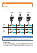
ATTENTION
Note on phase rotation in a group installation
If you use the wallbox in a charging group, the connection diagram shown on the communication module must be adapted individ-
ually for each wallbox in order to avoid a phase imbalance within the group. The phase rotation between the individual wallboxes
is described and illustrated in the next section.
ATTENTION
Checking the connection
Please ensure that the conductors that are pre-fixed to the terminals remain attached correctly after connecting the power supply
cable.


